
Latch tool

a technology of latching tool and toolstring, which is applied in the direction of tubing catchers, drilling accessories, and accessories for wellbore/wells. it can solve the problems of safety hazards for well operators, tool catcher devices that do not automatically operate, and catastrophic damage to toolstrings and wellbores

Inactive Publication Date: 2021-03-04
EXPRO NORTH SEA
View PDF0 Cites 0 Cited by
  • Summary
  • Abstract
  • Description
  • Claims
  • Application Information

AI Technical Summary

Benefits of technology

The present invention provides a latch tool for a wireline toolstring that can capture a coupling component to prevent the tool from falling down a wellbore if the wire breaks. The latch tool automatically captures the coupling component when the tension applied to the wire exceeds a predetermined value, but does not capture it if the tension is too low. It also acts as a shock absorbing function to slow down the toolstring gradually if it impacts the latch tool at speed. The latch tool may include a spring chamber and a latch assembly that can move axially relative to the anchor assembly, providing some free travel between them. The latch assembly may have multiple latch elements that are resiliently biased towards a latching configuration. These features enhance the automatic operation of the latch tool and improve its ability to capture the coupling component securely.

Problems solved by technology

If the tension exceeds the yield strength of the wire, the wire may break allowing the toolstring to fall back down the well and potentially causing catastrophic damage to the toolstring and the wellbore, and a safety hazard to operators of the well.
However, known tool catcher devices do not operate automatically and require manual intervention to select either a catch mode or a release mode.
Known tool catcher devices are not configured to operate according to the tension in the wire, and they cannot be adjusted to operate at different selectable tension values.

Method used


Image

  • Latch tool
  • Latch tool
  • Latch tool

Examples


Embodiment Construction

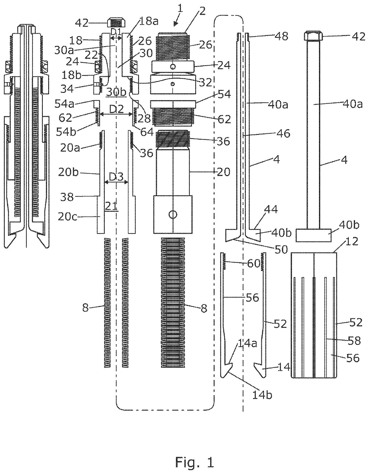
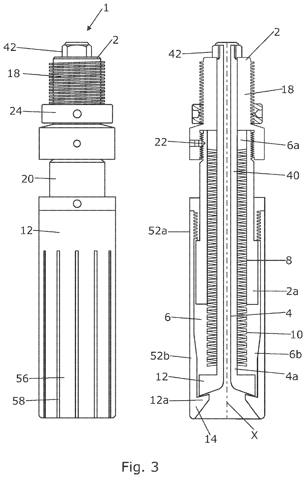
lass="d_n">[0023]The main components / assemblies of the bumper latch are shown in FIGS. 1 and 3. These include a substantially tubular anchor assembly 2 that has a longitudinal axis X. A core assembly 4 extends axially through the anchor assembly 2 and is mounted for sliding movement relative to the anchor assembly.

[0024]The anchor assembly 2 and the core assembly 4 together define a spring chamber 6 that extends parallel to the axis X and is located in the annular space between anchor assembly 2 and the core assembly 4. The upper end 6a of the spring chamber 6 is defined by the anchor assembly 2 and the lower end 6b is defined by the core assembly 4. The length L of the spring chamber 6 therefore changes as the core assembly 4 slides axially relative to the anchor assembly 2.

[0025]A compression spring 8 is located within the spring chamber 6 between the upper end 6a and the lower end 6b. In this embodiment the spring 8 comprises a plurality of disc springs (e.g. Belleville washers) ...


PUM


Abstract

A latch tool for a wireline toolstring includes an anchor assembly that is attached to a support structure. A core assembly is configured for axial movement relative to the anchor assembly. The anchor assembly and the core assembly provide a spring chamber having a length that changes with axial movement of the core assembly. A spring opposes axial movement of the core assembly. A latch assembly includes at least one latching element that captures a coupling component. The spring provides a bias force that opposes axial movement of the core assembly in a latching direction, but permits axial movement of the core assembly in the latching direction when an axial force applied to the core assembly exceeds the bias force.

Description

[0001]This application claims priority to PCT Patent Appln. No. PCT / GB2019 / 050728 filed Mar. 15, 2019, which claims priority GB Patent Appln. No. 1806838.7 filed Apr. 26, 2018, which are herein incorporated by reference.BACKGROUND OF THE INVENTION1. Technical Field[0002]The present invention relates to a latch tool for use within a pressure control rig-up and wireline toolstring.2. Background Information[0003]A pressure control rig up is a package of assemblies that is used to extend the pressure containment of a wellbore to accommodate a wireline tool string.[0004]A wireline toolstring is a package of one or more tools and / or instruments that is lowered into a wellbore for sensing / instrumentation and / or well bore manipulation purposes, particularly in the oil and gas production industry.[0005]The wireline toolstring is lowered into the wellbore and retrieved by means of a wire and a winch. Upon retrieval of the toolstring to surface and reaching the top of the well the toolstring c...

Claims


Application Information

Patent Timeline
IPC IPC(8): E21B19/10
CPCE21B19/10E21B19/008E21B31/18E21B23/01E21B40/00
Inventor MINNIS, ANDRE
Owner EXPRO NORTH SEA
Learn More