Press belt and shoe press roll

a belt and shoe technology, applied in the field of press belts and shoe press rolls, can solve the problems of large cracks likely to be generated in the outer peripheral surface, and the cracks are not easily generated in both edge regions, and achieve the effect of simple structur

Active Publication Date: 2010-04-27
YAMAUCHI CORP
View PDF20 Cites 0 Cited by
  • Summary
  • Abstract
  • Description
  • Claims
  • Application Information

AI Technical Summary

Benefits of technology

[0010]It is an object of the present invention to provide a press belt having a more simple structure than before, in which a crack is effectively prevented from being generated in both-end corresponding regions positioned so as to correspond to both ends of a press member in a width direction such as a press roll or a press shoe.
[0013]Stress is applied to the both-end corresponding regions of the press belt in traveling and width directions, so that twisting stress is applied thereto. According to the constitution of the present invention, since the thickness of the both-end corresponding region is small, flexibility in this region is enhanced. Therefore, when the twisting stress is applied to the both-end corresponding region, since the both-end corresponding region absorbs the twisting stress by flexible deforming, the crack is effectively prevented from being generated.
[0015]According to one embodiment, an outermost region having the same thickness as that of the center region is provided outside the both-end corresponding region. In general, a felt is placed between the press belt and the object to be pressed and the object passes through the pressing means together with the felt. When the outermost region of the press belt has the same thickness as that of the center region, since both ends of the felt in a width direction can be stably supported, free movement of the felt can be controlled.
[0018]When the press belt comprises the outermost region having the same thickness as that of the center region outside the both end corresponding region, many drainage grooves may be formed in outer peripheral surfaces of the center region and the outermost region along the travel direction of the belt. When the drainage grooves are provided in the outermost region, since flexibility of the outermost region can be enhanced, an effect of preventing the crack generation can be enhanced.
[0021]In another aspect of the present invention, a press belt comprises a reinforcing layer and an upper elastic layer formed on the reinforcing layer, and the upper elastic layer comprises both-end corresponding regions positioned so as to correspond to both ends of the pressing means in a width direction and a center region positioned between the both-end corresponding regions. This embodiment is characterized in that many drainage grooves extending along the travel direction of the belt are formed in the center region of the upper elastic layer but a drainage groove is not formed in the both-end corresponding region. The crack is easily generated in the bottom of the drainage groove positioned in the both-end corresponding region. Thus, according to this embodiment, the drainage groove is not formed in the both-end corresponding region to prevent the crack from being generated. In this embodiment, the thickness of the both-end corresponding region may be the same as that of the center region.
[0022]In the above embodiment, an outermost region having a drainage groove may be provided outside the both-end corresponding region. Since the flexibility of the outermost region is enhanced because of the drainage grooves in the outermost region, the crack is more effectively prevented from being generated.

Problems solved by technology

However, since excessive bending or pressing is repeated on the press belt, especially the shoe press belt, a crack which is likely to be generated in the outer peripheral surface is a big problem in view of resistance.
In this case, it is thought that there is an effect that the abrasion resistance or pressed deformation resistance is maintained in the center region and the crack is not easily generated in both edge regions.

Method used


Image

  • Press belt and shoe press roll
  • Press belt and shoe press roll
  • Press belt and shoe press roll

Examples


Embodiment Construction

[0034]An embodiment of the present invention will be described with reference to the drawings hereinafter.

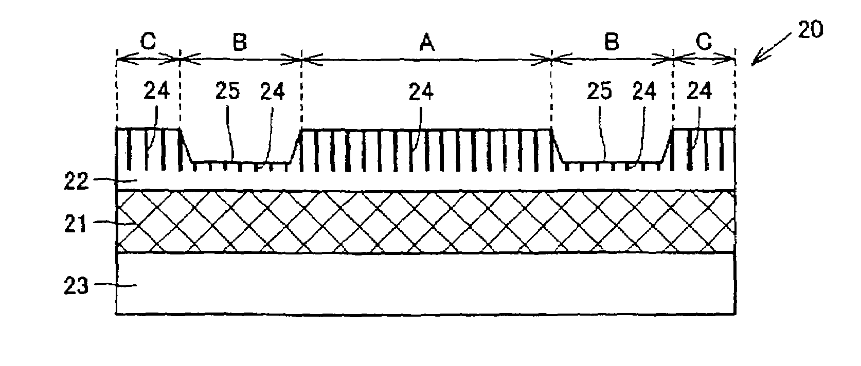
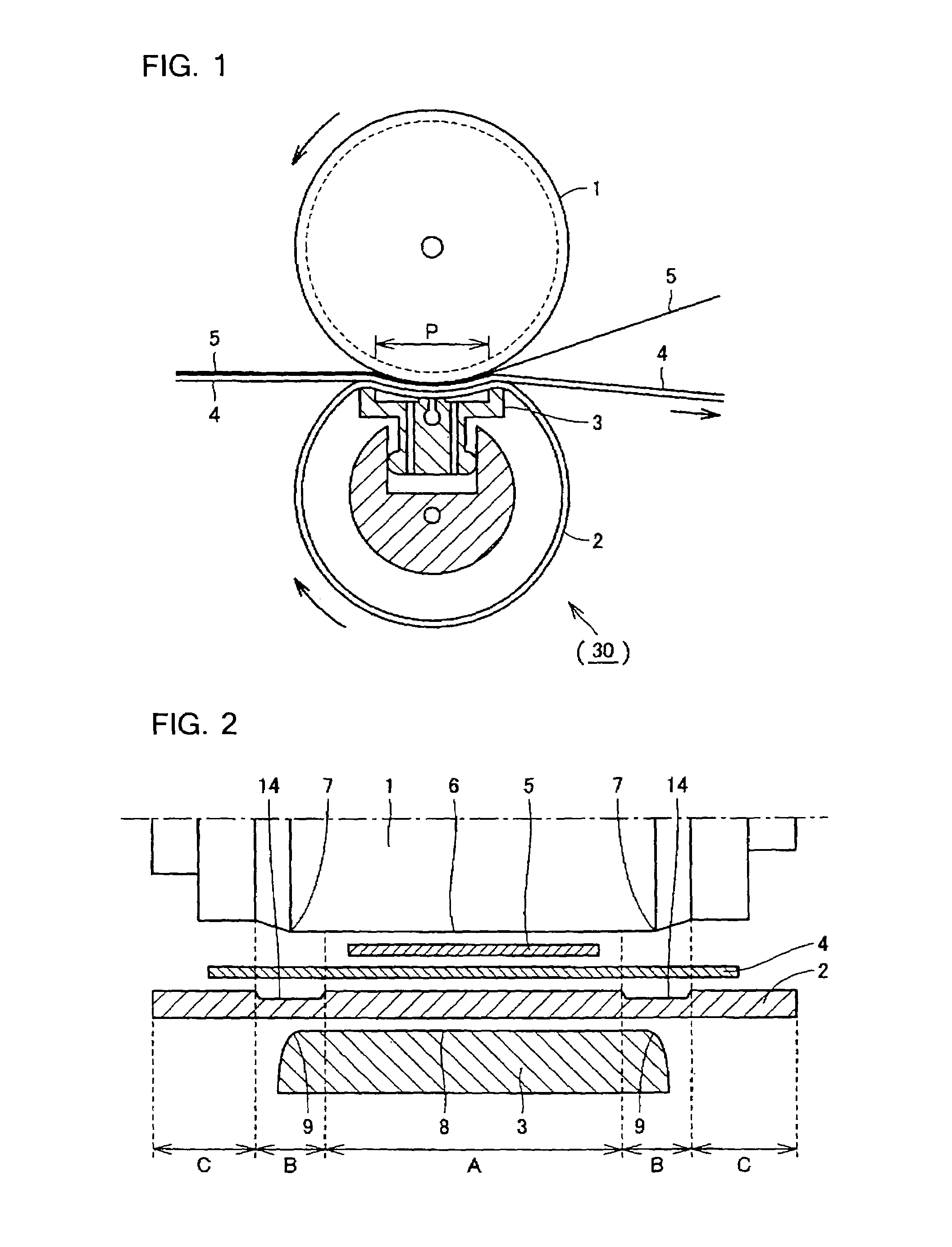
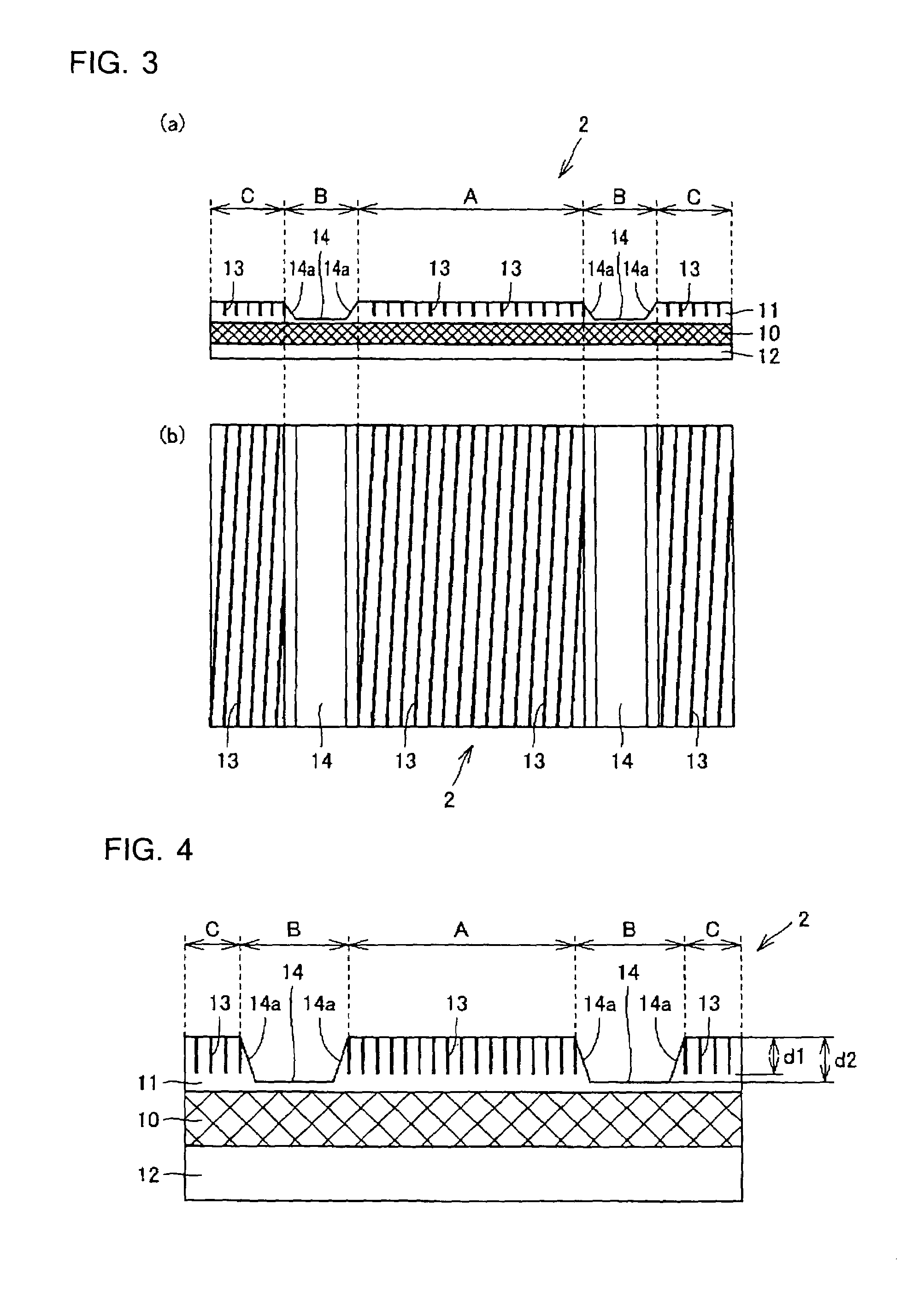
[0035]FIG. 1 is a view showing a section of a shoe press system in a travel direction used in a pressing process of a paper machine. The shoe press system comprises a press roll as pressing means 1, a press belt 2 opposed to the press roll 1, and a press shoe positioned inside the press belt 2 and serving as pressing means 3. In addition, according to the system shown in FIG. 1, although a shoe press roll 30 is so constituted that the press shoe 3 is covered with the press belt 2 and the press belt 2 is assembled so as to be in the shape of a roll as an external cylinder, the press belt 2 is not necessarily assembled so as to be in the shape of the roll and it may be used as an endless belt as it is.

[0036]A size of this kind of the press belt 2 is 2 to 15 m in width and 1 to 30 m in peripheral length and 2 to 10 mm in thickness in general.

[0037]The press roll 1 is positioned out...


PUM

PropertyMeasurementUnit
lengthaaaaaaaaaa
widthaaaaaaaaaa
widthaaaaaaaaaa

Abstract

A press belt (2) comprises both-end corresponding regions B positioned so as to correspond to both ends of a press roll (1) or a press shoe (3) in a width direction and having a small thickness and a center region A positioned between the both-end corresponding regions B and having a thickness larger than that of the both-end corresponding region B.

Description

TECHNICAL FIELD[0001]The present invention relates to a press belt and shoe press roll used to press an object in various kinds of industries such as a paper industry, a magnetic recording medium manufacturing industry, a fiber industry and the like.BACKGROUND ART[0002]In various kinds of industries, belt press in which a continuous long object to be pressed is put on a press belt and the object is pressed between one press member positioned inside the press belt and the other press member positioned outside the press belt is used. Here, the press member is a press roll or a press shoe. As an example of the belt press, there is a shoe press as dewatering press in the paper industry.[0003]The shoe press will be briefly described taking the paper industry as an example. It is a pressing (drying) method in which an object (wet paper web) to be pressed is put on an outer peripheral surface of a press belt and pressed between a press roll positioned outside the press belt and serving as ...

Claims


Application Information

Patent Timeline
Patent Type & Authority Patents(United States)
IPC IPC(8): D21F3/02B30B3/02B30B5/04D21F3/00
CPCD21F3/0218D21F3/0227Y10S162/901Y10T428/24479Y10T428/2457Y10T442/2369Y10T442/3854D21F3/00D21F3/02
Inventor HIKITA, TAKAHISAWATANABE, ATSUO
Owner YAMAUCHI CORP
Why Eureka
Try Eureka