Ultrasonic flow meter
a flow meter and ultrasonic technology, applied in the direction of volume/mass flow measurement, measurement devices, instruments, etc., can solve the problems of large number of components and high cost, and achieve the effect of reducing the cost of components, reducing the number of components, and improving the variation of measuremen
- Summary
- Abstract
- Description
- Claims
- Application Information
AI Technical Summary
Benefits of technology
Problems solved by technology
Method used
Image
Examples
first exemplary embodiment
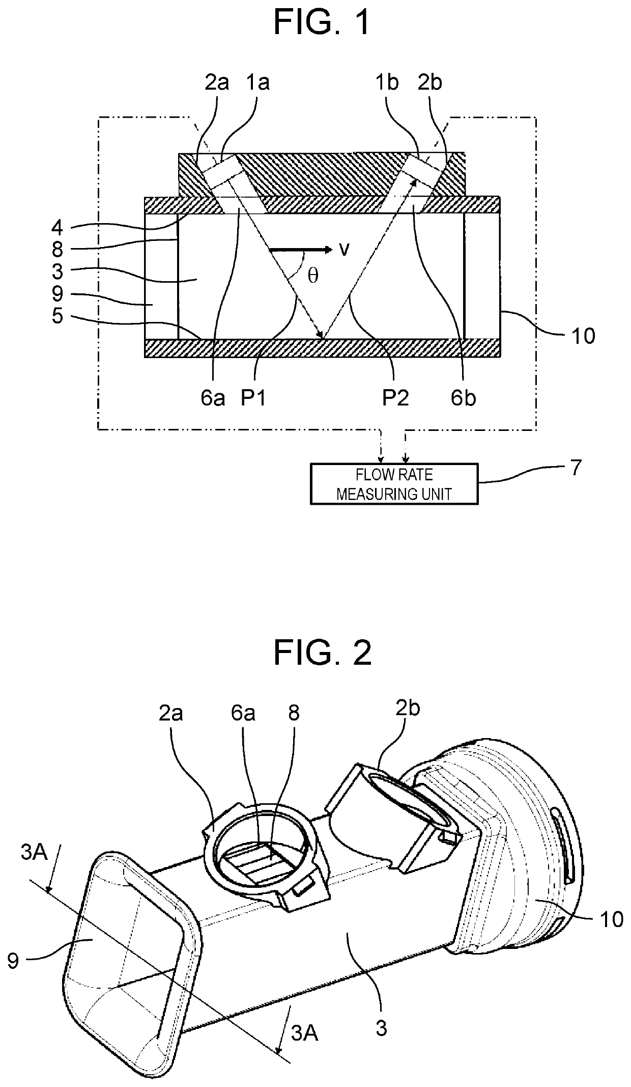
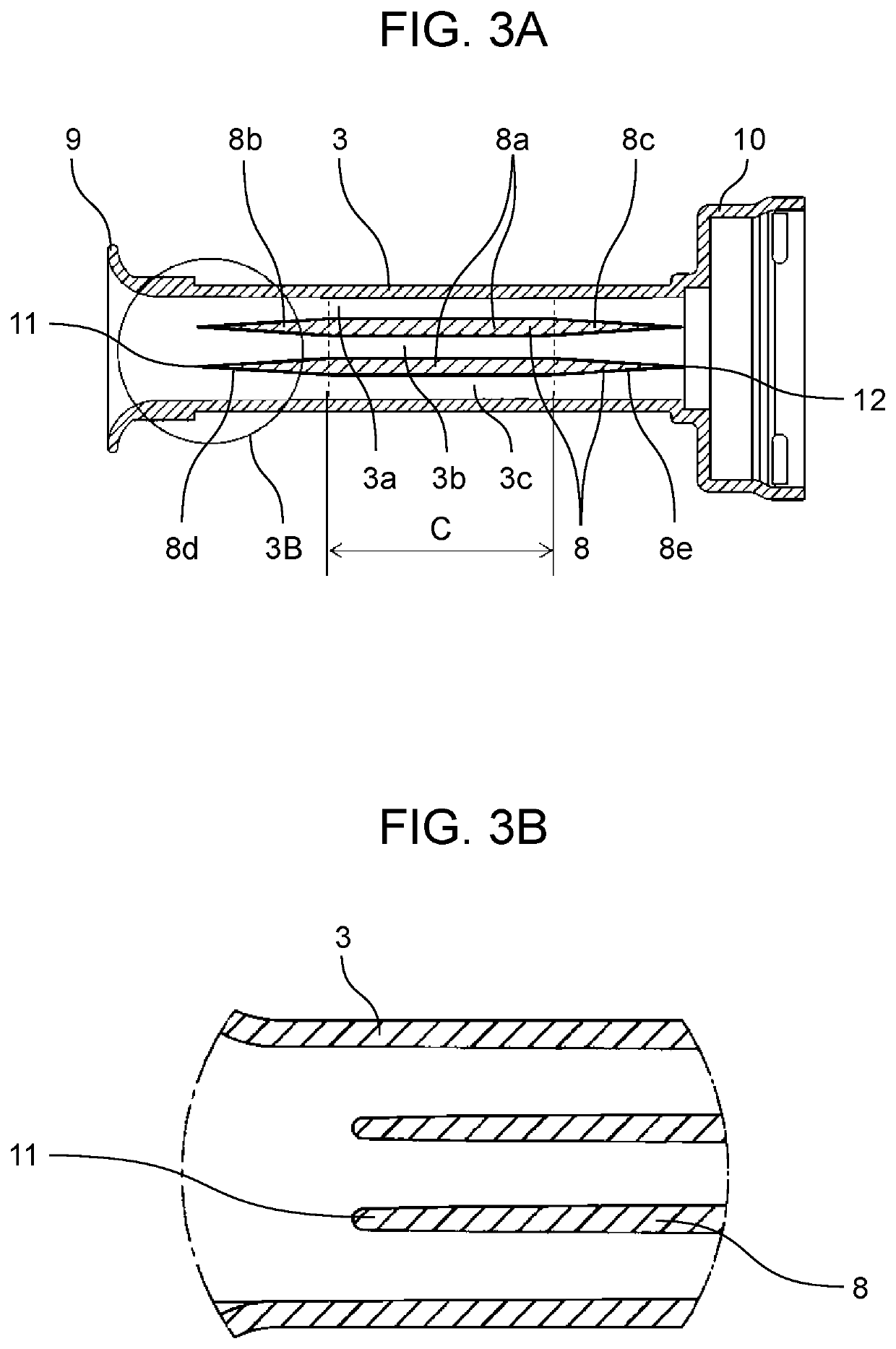
[0016]FIG. 1 is a cross-sectional view of an ultrasonic flow meter according to a first exemplary embodiment. FIG. 2 is a perspective view of a measurement flow path of the ultrasonic flow meter according to the first exemplary embodiment. FIG. 3A is a cross-sectional view taken along line 3A-3A of FIG. 2. FIG. 3B is an enlarged view of part 3B of FIG. 3A.
[0017]As illustrated in FIGS. 1 and 3A, measurement flow path 3 for passing a fluid to be measured from measurement flow path inlet 9 to measurement flow path outlet 10 is a pipe for passing the fluid to be measured, and is divided into three layered flow paths 3a, 3b, 3c by two partition plates 8. Openings 6a, 6b through which ultrasonic waves propagate so that the ultrasonic waves are transmitted and received diagonally to measurement flow path 3 are formed on measurement flow path upper surface 4, and ultrasonic sensors 1a, 1b are fixed to mounting portions 2a, 2b so that the ultrasonic waves are reflected by measurement flow pa...
second exemplary embodiment
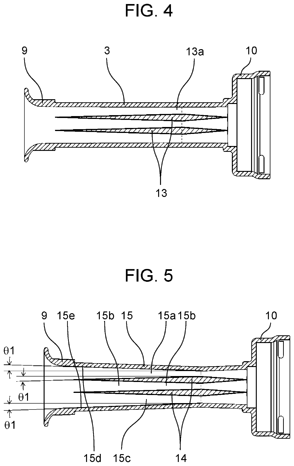
[0028]FIG. 4 is a cross-sectional view of an ultrasonic flow meter according to a second exemplary embodiment in a direction perpendicular to a partition plate. A cross-sectional view in a direction parallel to partition plates 8 is similar to that in FIG. 1.
[0029]In the ultrasonic flow meter, it is important that separation of a fluid is reduced mainly in a region measured by ultrasonic sensors 1a, 1b in a case of a forward flow. In the present exemplary embodiment, portion 13a having the maximum thickness of partition plate 13 is not a midpoint of partition plate 13 but closer to a trailing edge (side of measurement flow path outlet 10) than to a front edge (side of measurement flow path inlet 9).
[0030]With this configuration, the ultrasonic flow meter in the present exemplary embodiment can suppress the separation of the fluid in the region where the ultrasonic waves are measured in the case of the forward flow, and can perform more stable measurement.
[0031]Furthermore, if a surf...
third exemplary embodiment
[0032]FIG. 5 is a cross-sectional view of an ultrasonic flow meter according to a third exemplary embodiment in a direction perpendicular to a partition plate. A cross-sectional view in a direction parallel to partition plates 14 is similar to that in FIG. 1.
[0033]In the present exemplary embodiment, among inner walls of measurement flow path 15, inner walls 15d, 15e parallel to partition plates 14 are provided with gradients symmetrical with gradients of partition plates 14 facing inner walls 15d, 15e. That is, in order to make shapes of three layered flow paths 15a, 15b, 15c formed by measurement flow path 15 being divided by two partition plates 14 into the same shape, inner walls 15d, 15e of the flow path are also provided with the same gradient as draft 01 provided on partition plates 14.
[0034]If shapes of regions where a fluid to be measured flows in the layered flow paths are different, a flow velocity distribution and a pressure loss change for each layer, and a flow velocit...
PUM
 Abstract
Description
Claims
Application Information
 - R&D
- Intellectual Property
- Life Sciences
- Materials
- Tech Scout
- Unparalleled Data Quality
- Higher Quality Content
- 60% Fewer Hallucinations
Browse by: Latest US Patents, China's latest patents, Technical Efficacy Thesaurus, Application Domain, Technology Topic, Popular Technical Reports.
© 2025 PatSnap. All rights reserved.Legal|Privacy policy|Modern Slavery Act Transparency Statement|Sitemap|About US| Contact US: help@patsnap.com


