
Method for rewriting semiconductor storage device and the semiconductor storage device

Active Publication Date: 2017-12-14
PANASONIC SEMICON SOLUTIONS CO LTD
View PDF0 Cites 0 Cited by
  • Summary
  • Abstract
  • Description
  • Claims
  • Application Information

AI Technical Summary

Benefits of technology

The present disclosure provides a method and device for rewriting a semiconductor storage device that reduces the occurrence of unstable-waveform application pulses and variation in pulse width when timings for applying write voltages have deviated due to wiring delay. This ensures a stable application of high voltage to memory cells and reduces the likelihood of data loss or malfunction during the rewriting process.

Problems solved by technology

This makes it difficult to apply a high voltage to the MOS transistors.
For example, it becomes difficult to apply a bias voltage of 3 V to a MOS transistor in a 1.1 V system.
However, for example, in a simultaneous pulse method which is a method for applying write voltages simultaneously in a state where a pre-charge voltage is applied to the drains and sources of MOS transistors, the timings for applying the write voltages may deviate due to wiring delay etc.
In this way, in the simultaneous pulse method, the waveforms of pulses applied to change the resistance values of variable resistance elements are unstable.

Method used


Image

  • Method for rewriting semiconductor storage device and the semiconductor storage device
  • Method for rewriting semiconductor storage device and the semiconductor storage device
  • Method for rewriting semiconductor storage device and the semiconductor storage device

Examples


embodiment 1

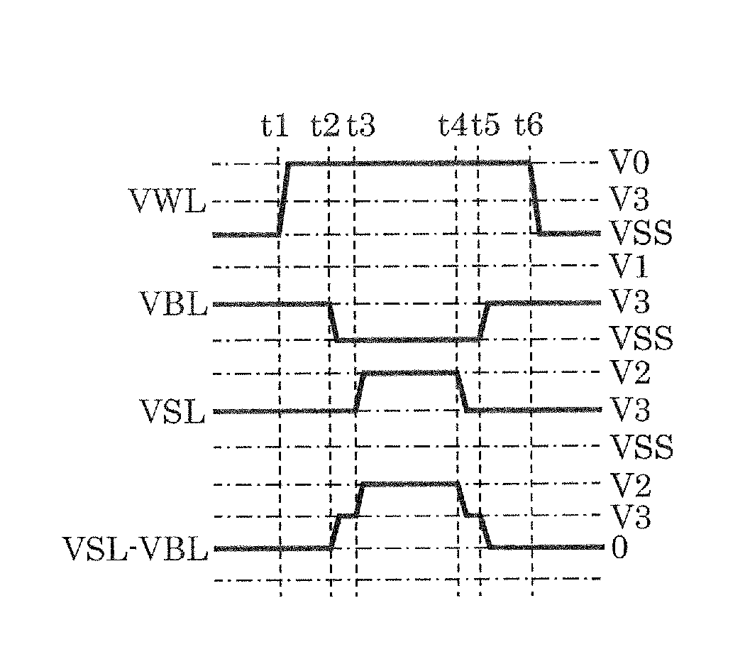
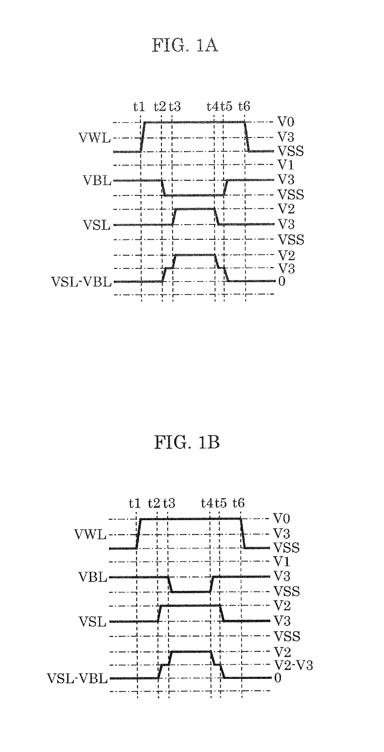
[0105]Hereinafter, Embodiment 1 is described with reference to FIG. 1A to FIG. 4C.

[0106]FIGS. 1A and 1B are each a timing chart of rewriting semiconductor storage device 1 according to Embodiment 1.

[0107]FIGS. 1A and 1B are each indicates a bias state at the time when a selected memory cell is set to LR.

[0108]Here, at least one word line is selected from among the plurality of word lines as a selected word line. In addition, at least one bit line is selected from among the plurality of bit lines as a selected bit line, and at least one source line is selected from among the plurality of source lines as a selected source line.

[0109]First, pre-charge voltage V3 is applied to both of the plurality of bit lines and the plurality of source lines (a first rewriting step). Next, a rewrite voltage (VSS (=0 V), V1 or V2) is applied to one of the selected bit line or the selected source line (a second rewriting step). Next, a rewrite voltage (VSS (=0 V), V1 or V2) is applied to both of the se...

embodiment 2

[0138]Hereinafter, Embodiment 2 is described with reference to FIG. 5A to FIG. 5E.

[0139]The configuration of semiconductor storage device 2 according to this embodiment is the same as that of semiconductor storage device 1, and thus descriptions thereof are not repeated. FIGS. 5A to 5E are each a timing chart of rewriting semiconductor storage device 2 according to Embodiment 2.

[0140]FIGS. 5A to 5E each illustrate a bias state at the time when a selected memory cell is set to LR.

[0141]Here, at least one word line is selected from among the plurality of word lines as a selected word line. In addition, at least one bit line is selected from among the plurality of bit lines as a selected bit line, and at least one source line is selected from among the plurality of source lines as a selected source line.

[0142]First, pre-charge voltage V3 is applied to both of the plurality of bit lines and the plurality of source lines (a first rewriting step). Next, both of the selected bit line and t...

embodiment 3

[0150]Hereinafter, Embodiment 3 is described with reference to FIG. 6.

[0151]The configuration of semiconductor storage device 3 according to this embodiment is the same as that of semiconductor storage device 1, and thus descriptions thereof are not repeated.

[0152]FIG. 6 is a timing chart of rewriting semiconductor storage device 3 according to Embodiment 3.

[0153]FIG. 6 indicates a bias state at the time when a selected memory cell is set to LR.

[0154]Here, at least one word line is selected from among the plurality of word lines as a selected word line. In addition, at least one bit line is selected from among the plurality of bit lines as a selected bit line, and at least one source line is selected from among the plurality of source lines as a selected source line.

[0155]First, pre-charge voltage V3 is applied to both of the plurality of bit lines and the plurality of source lines (a first rewriting step). Next, both of the selected bit line and the selected source line are grounde...


PUM


Abstract

A method for rewriting a semiconductor storage device includes: a first rewriting step of applying a pre-charge voltage to both of a plurality of bit lines and a plurality of source lines; a second rewriting step of applying a rewrite voltage to one of a selected bit line or a selected source line; a third rewriting step of applying a rewrite voltage to both of the selected bit line and the selected source line; a fourth rewriting step of applying a pre-charge voltage to one of the selected bit line or the selected source line; and a fifth rewriting step of applying a pre-charge voltage to both of the selected bit line and the selected source line.

Description

CROSS REFERENCE TO RELATED APPLICATIONS[0001]This application is a U.S. continuation application of PCT International Patent Application Number PCT / JP2016 / 001123 filed on Mar. 2, 2016, claiming the benefit of priority of Japanese Patent Application Number 2015-067676 filed on Mar. 27, 2015, the entire contents of which are hereby incorporated by reference.BACKGROUND1. Technical Field[0002]The present disclosure relates to a method for rewriting a semiconductor storage device and the semiconductor storage device.2. Description of the Related Art[0003]Semiconductor storage devices are used for embedded devices, computers, information communication devices etc. Recent years have seen active technical' development, for semiconductor storage devices, such as increase in capacity, size reduction, high-speed rewriting, high-speed reading, saving in power consumption for operation.[0004]In particular, a resistive memory (resistive random access memory (ReRAM)) in which a variable resistance...

Claims


Application Information

Patent Timeline
IPC IPC(8): G11C13/00
CPCG11C13/0028G11C13/0026G11C13/0061G11C13/0069G11C2013/0071G11C2213/79G11C2213/82
Inventor NAGAI, HIROYASU
Owner PANASONIC SEMICON SOLUTIONS CO LTD
Learn More