Real-Time Clock Device

a real-time clock and clock technology, applied in the direction of generating/distributing signals, oscillation generators, electrical equipment, etc., can solve the problems of real-time clock devices not being able to perform the required functions, cracks may occur due to the stress acting on solder,

Pending Publication Date: 2021-09-16
SEIKO EPSON CORP
View PDF8 Cites 0 Cited by
  • Summary
  • Abstract
  • Description
  • Claims
  • Application Information

AI Technical Summary

Benefits of technology

The patent describes a real-time clock device that solves problems by using a resonator, an oscillation circuit, a clocking circuit, a functional circuit, and a package. The device also includes external terminals for power supply, clocking, and functional control. The device further includes a switching circuit that can connect or disconnect the functional circuit from the external control terminals. The technical effect of the patent is to provide a practical and efficient solution for generating accurate clocking information for information processing, and to enable flexible and reliable control of the functional circuit.

Problems solved by technology

In such solder mounting, cracks may occur due to the stress acting on the solder.
As a result, the real-time clock device may not be able to perform the required functions due to a coupling failure at the external terminals.

Method used


Image

  • Real-Time Clock Device
  • Real-Time Clock Device
  • Real-Time Clock Device

Examples


Embodiment Construction

[0010]Here, embodiments of the present disclosure will be described in the following order.

[0011](1) Configuration of Real-Time Clock Device

[0012](2) Other Embodiments

(1) Configuration of Real-Time Clock Device

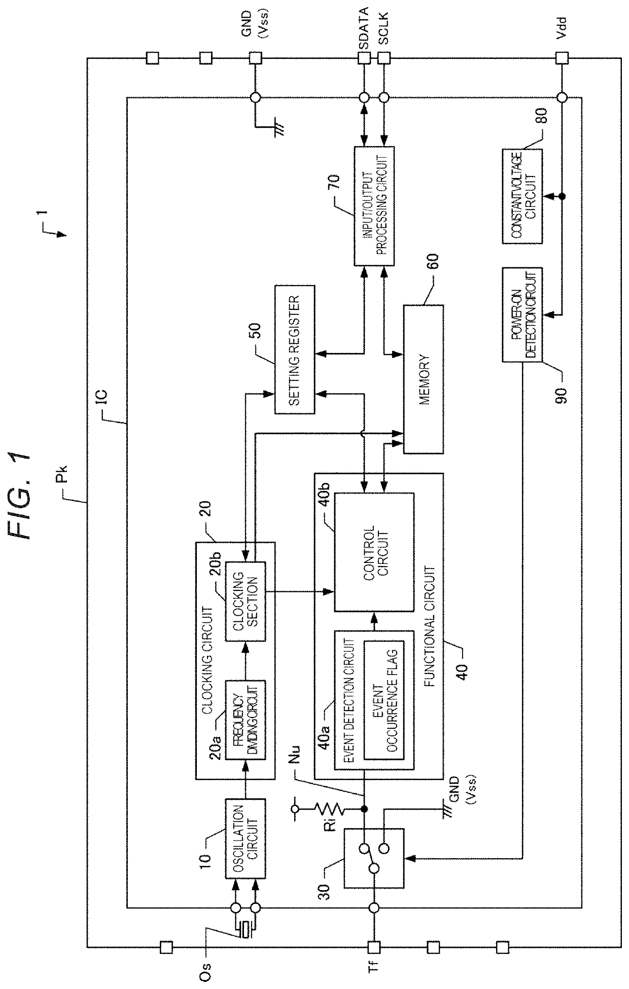
[0013]FIG. 1 is a block diagram showing a configuration of a real-time clock device 1 according to a first embodiment. The real-time clock device 1 according to the present embodiment is a device in which a resonator Os and an integrated circuit (IC) are housed in a package Pk. In FIG. 1, external terminals are schematically shown by squares overlapped on rectangular sides indicating the package Pk. The external terminals are contacts provided on the package Pk and are soldered to a pad of a substrate.

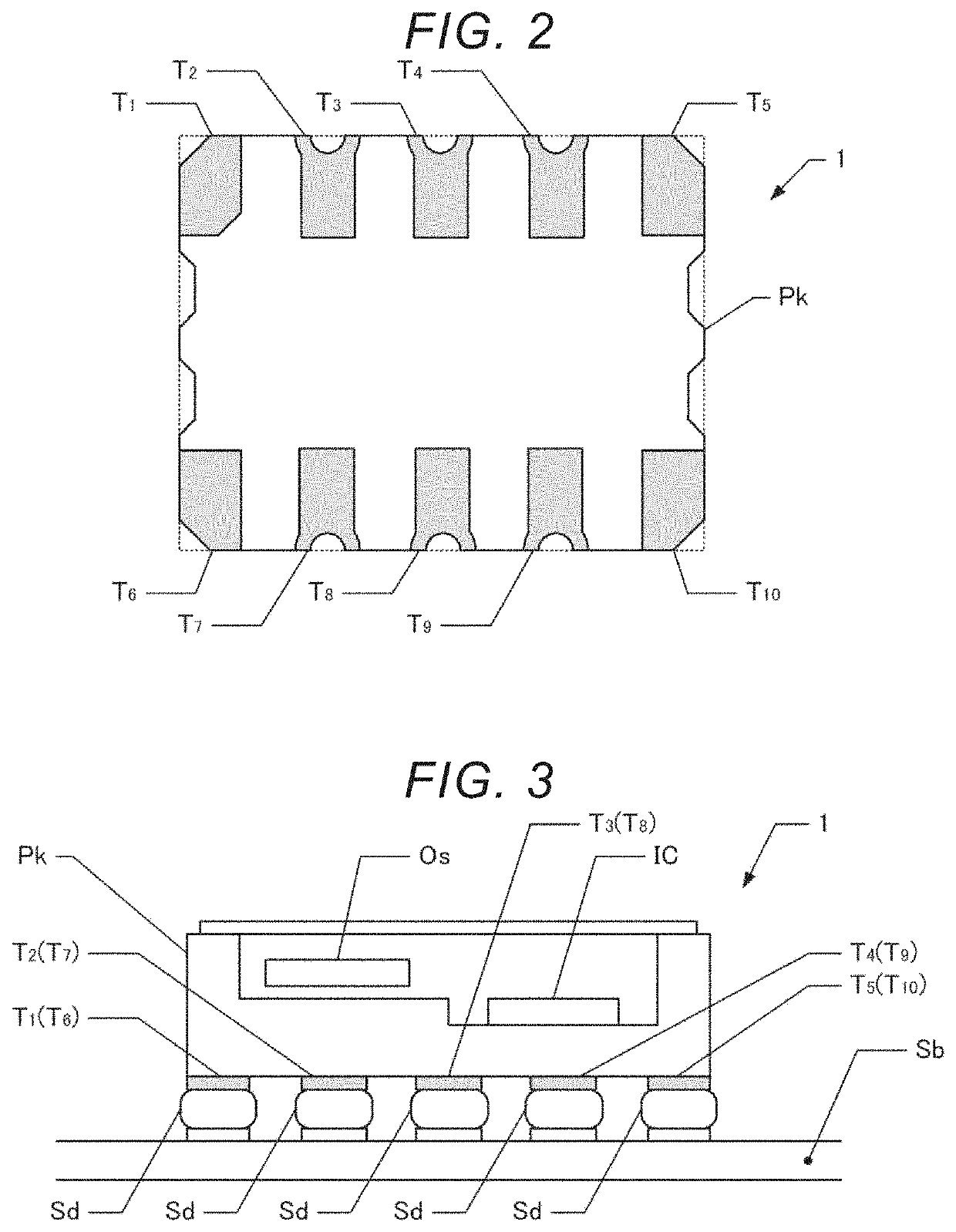
[0014]FIG. 2 is a diagram showing a state in which the package Pk is viewed from the back side. The back surface is a surface facing the mounting surface of the substrate in a state of being mounted on the substrate. In FIG. 2, the external terminals are colored in gray. That is,...


PUM


Abstract

A real-time clock device includes a package that houses a resonator, an oscillation circuit, a clocking circuit, and a functional circuit, and on which external terminals are formed. The external terminals include a high-potential power supply terminal coupled to a high-potential power supply, a low-potential power supply terminal coupled to a low-potential power supply, a clocking signal terminal used at least for controlling the clocking circuit, and a functional signal terminal used for controlling the functional circuit, the functional signal terminal is arranged outside the high-potential power supply terminal, the low-potential power supply terminal, and the clocking signal terminal in a direction in which the external terminals are arranged, and the real-time clock device further includes a switching circuit that switches between a state in which the functional signal terminal and the functional circuit are coupled and a state in which the functional signal terminal and the functional circuit are not coupled.

Description

[0001]The present application is based on, and claims priority from JP Application Serial Number 2020-045034, filed Mar. 16, 2020, the disclosure of which is hereby incorporated by reference herein in its entire.BACKGROUND1. Technical Field[0002]The present disclosure relates to a real-time clock device.2. Related Art[0003]In the related art, real-time clocks that generate clocking information by clocking circuits are known. The real-time clock is used for various purposes. For example, purposes such as an event recorder for recording clocking information when an event occurs and an interrupt output for outputting a signal according to a lapse of a specific period are known. JP-A-2009-26169 describes examples of the former, and JP-A-2009-32142 describes examples of the latter. Further, as described above, a configuration is known that real-time clocks and functions for various purposes are realized by circuits in one package.[0004]In the configuration in which circuits having real-t...

Claims


Application Information

Patent Timeline
IPC IPC(8): H03H9/13H03B5/32H03H9/17G06F1/14G06F1/08
CPCH03H9/13H03B5/32G06F1/08G06F1/14H03H9/17H03B5/06H03H9/0542H03H9/1014
Inventor USUDA, TOSHIYA
Owner SEIKO EPSON CORP
Why Eureka
Try Eureka