Apparatus and method for in-situ electrosleeving and in-situ electropolishing internal walls of metallic conduits

a technology of electropolishing and conduit, which is applied in the direction of electrolysis process, electrolysis components, sealing devices, etc., can solve the problems of insufficient thin coatings inside the tubes, limitations, and inability to reestablish original mechanical properties, and achieve the effect of avoiding the disintegration of soluble/consumable anodes

Active Publication Date: 2021-09-23
INTEGRAN TECH
View PDF0 Cites 5 Cited by
  • Summary
  • Abstract
  • Description
  • Claims
  • Application Information

AI Technical Summary

Benefits of technology

[0090]As used herein, the term “soluble / consumable active anode material” means the metallic material(s) oxidized on the positive electrode to form ions which dissolve in the electrolyte and cathodically deposit on the workpiece. The soluble / consumable active anode material can be a layer on an inert / permanent substrate to provide for a soluble / consumable anode which, while being dissolved during anodic oxidation, retains its structural integrity, i.e., the disintegration of the soluble / consumable anode is avoided.

Problems solved by technology

As discussed above, the various “electrosleeving processes” disclosed in the prior art and applied, e.g., to inside tube surfaces of nuclear steam generator tubes, have limitations.
Thin coatings inside the tube are frequently insufficient to reestablish the original mechanical properties, if this is a desired objective.
The method of handling and sealing the probe against the inside tube wall can, at times, be challenging.
Moving the entire probe back and forth during the plating operation results in increased wear and deterioration of the polymer seals as well as the incorporation of seal debris in the metallic coating.
This frequently causes leakage of the corrosive electrolyte out of the “sealed compartment” causing further degradation.
Leakage of the heat-transfer medium into the probe contaminates the electrolyte solution and / or the various process and washing fluids used in the process.
In addition, none of the prior art teachings deals with the rough surface finish obtained with thicker electrodeposited coatings (≥0.1 mm), the quality of the fluid-tight seal, and how the tightness of the seals is affected when a probe filled with electrolyte is moved along the tube inside surface while the internal diameter of the tube constantly changes while a metallic layer is being deposited.
Probe insertion / removal may be difficult due to the location of the damaged area and the geometry of the tubing, e.g., in long and more complex piping systems involving elbows, tees, piping of various inner diameter, etc.
The application of a suitable sleeve in regions other than straight areas, such as bends, elbows, tees and the like can be difficult as well.
Due to the design of prior art electrosleeving probes their use for electropolishing has heretofore not been feasible.
Electropolishing typically requires much higher current densities and solution flow rates than used in electroplating and the massive amounts of gas generated by the electropolishing process cannot be managed by these devices.

Method used


Image

  • Apparatus and method for in-situ electrosleeving and in-situ electropolishing internal walls of metallic conduits
  • Apparatus and method for in-situ electrosleeving and in-situ electropolishing internal walls of metallic conduits
  • Apparatus and method for in-situ electrosleeving and in-situ electropolishing internal walls of metallic conduits

Examples


Embodiment Construction

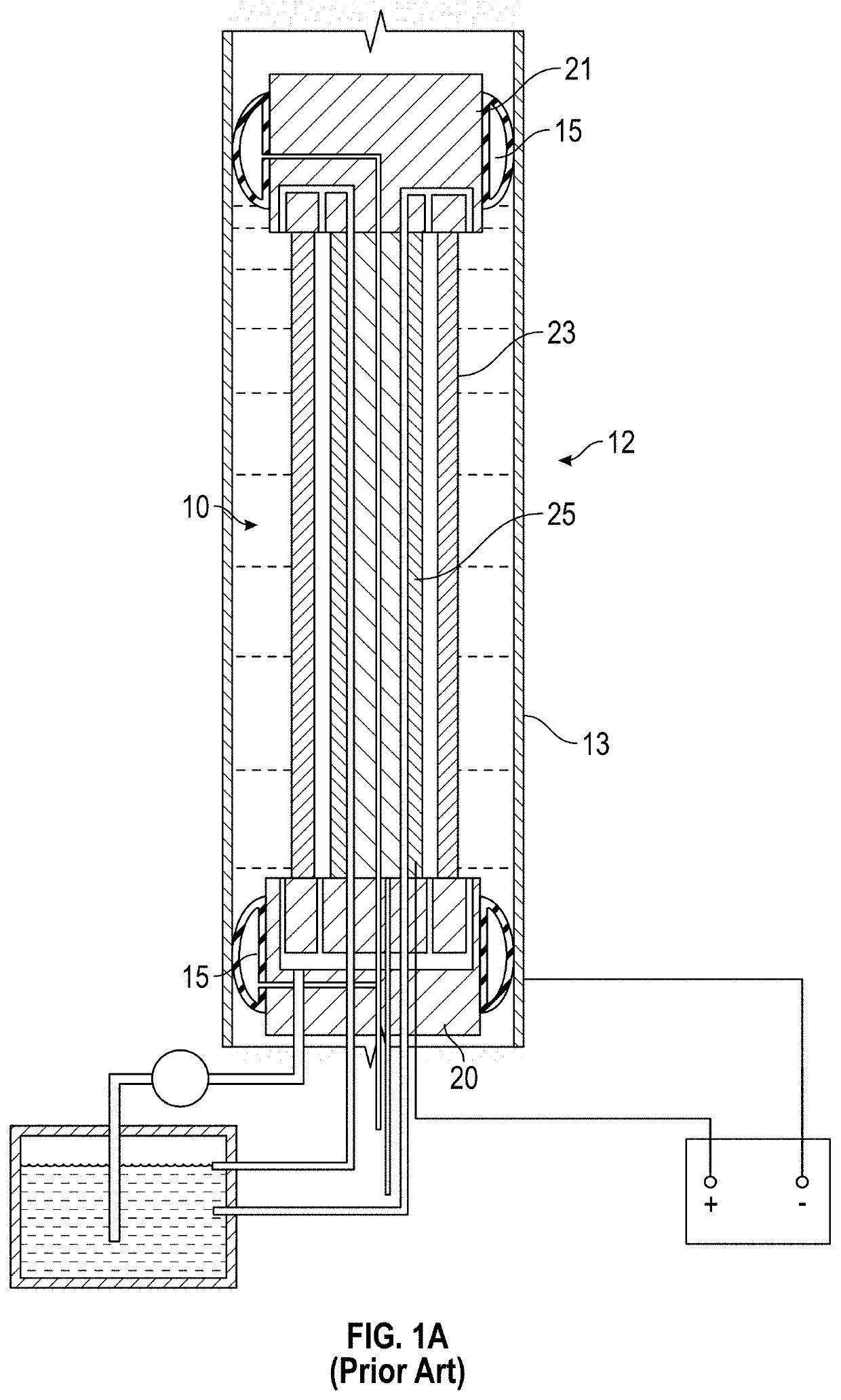
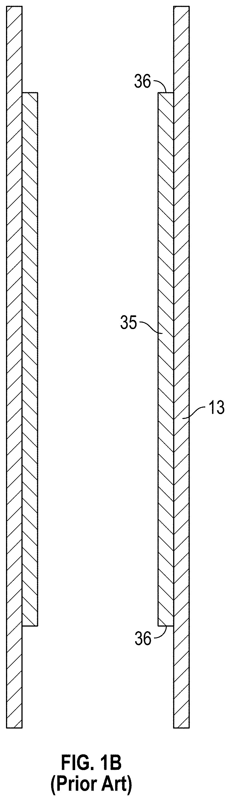
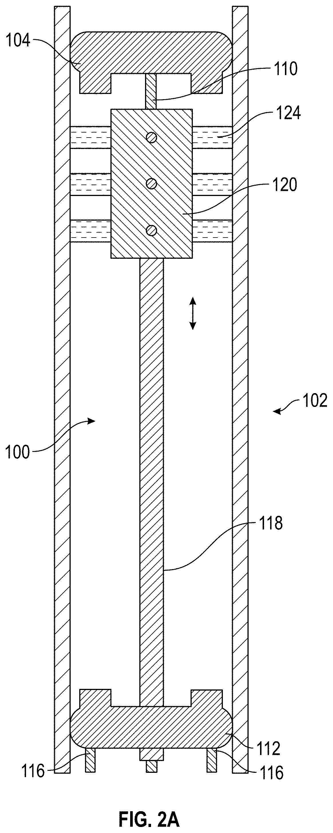
present disclosure relates to an electrolytic cell apparatus for use with several electrolytic processes which comprises the steps of: positioning a probe containing at least one non-conductive head cap, a non-conductive end cap and at least one non-conductive counter-electrode assembly into a hollow conduit, representing the workpiece to be processed; inflating all the terminal ends of the probe to seal off a compartment defined by the internal surface of the hollow conduit and the end and head caps of the probe; thereby creating a defined “electrolytic cell volume”; and by connecting the electrolytic cell to one or more external fluid reservoirs by means of a suitable fluid circulation system. A pump is used to circulate various fluids, including electrolyte into, into and out of the defined “electrolytic cell volume”. After cleaning and activating the workpiece surface with washing steps in between, electrical connections are made to the workpiece to be processed and to one or mo...


PUM

PropertyMeasurementUnit
inner diameteraaaaaaaaaa

Abstract

An apparatus and system for in-situ electropolishing and/or for in-situ electroforming a structural or functional reinforcement layer such as a sleeve of a selected metallic material on the internal surfaces of metallic tubular conduits are described. The apparatus and system can be employed on straight tubes, tube joints to different diameter tubes or face plates, tube elbows and other complex shapes encountered in piping systems. The apparatus includes components which can be independently manipulated and assembled on or near a degraded site and, after secured in place, form an electrolytic cell within the workpiece. The apparatus contains counter-electrodes which can be moved relative to the workpiece surface during the electroplating and/or electropolishing operation to provide flexibility in selecting and employing electropolishing process parameters and electroplating process parameters to design and optimize the surface roughness as well as the size, shape and properties of the electrodeposited reinforcing layer(s).

Description

[0001]This invention was made with government support under contracts N00014-14-C-0199 (2014) and N00014-18-C-1048 (2018) awarded by the Office of Naval Research (ONR). The Government has certain rights in this invention and the invention may be manufactured and used by or for the Government for Government purposes without the payment of any royalties thereon or therefore.FIELD OF THE INVENTION[0002]This invention is directed to a process and apparatus for in-situ electropolishing and / or in-situ electroplating metallic material layers onto the internal diameter of one or more tubular parts in an electrolytic cell formed in part by the host tubular conduit using direct (D.C.) or pulsed current. At their respective ends, the metallic material layers or sleeves can have smooth, tapered transition zones to the host tubing to which they adhere. This invention relates particularly to a process and apparatus for selectively electroplating a metal patch and / or sleeve onto the interior surfa...

Claims


Application Information

Patent Timeline
Patent Type & Authority Applications(United States)
IPC IPC(8): C25F3/16C25F7/00C25D7/04C25D3/38C25D3/12
CPCC25F3/16C25F7/00C25D3/12C25D3/38C25D7/04C25D5/04C25D17/00C25D17/004C25D17/007C25D17/12C25D5/16C25D5/18C25D5/34C25D3/20
Inventor PALUMBO, GINOMONACO, LEOMCCREA, JONATHANTOMANTSCHGER, KLAUSLIMOGES, DAVEMILLS, MICHAEL
Owner INTEGRAN TECH
Why Eureka
Try Eureka