Wire position correction method and wire position correction apparatus

a technology of position correction and wire position, which is applied in the direction of windings, dynamo-electric components, and magnetic circuit shapes/forms/constructions, etc., can solve the problems of the tip end position not being corrected with favorable accuracy, and the return range of the tip end portion, so as to achieve favorable accuracy, favorable accuracy, and favorable accuracy

Pending Publication Date: 2021-09-23
HONDA MOTOR CO LTD
View PDF0 Cites 0 Cited by
  • Summary
  • Abstract
  • Description
  • Claims
  • Application Information

AI Technical Summary

Benefits of technology

[0024](6) The wire position correction apparatus according to the present invention includes the holding apparatus that holds the tip end portion of the wire leg portion protruding from the slot of the stator core and the turning mechanism that supports the holding apparatus and turns the holding apparatus about the center axis passing through the bent portion or the base point on the tip end portion side with respect to the bent portion such that the tip end position of the wire leg portion moves in the direction approaching the reference position. According to the present invention, the holding apparatus is turned by the turning mechanism in a state in which the tip end portion of the wire leg portion is held by the holding apparatus, thereby bending the wire leg portion. Thus, the tip end position can approach the reference position without the need for shifting the position of the slot-side portion of the wire leg portion with respect to the base point or bending such a portion. Consequently, as compared to the case in which the base of the wire leg portion is bent as in the typical case, the return range of the tip end portion due to the spring back after bending can be narrowed. With this configuration, the tip end position of the target wire leg portion can be corrected with favorable accuracy.
[0025](7) The wire position correction apparatus according to the present invention includes the turning angle calculation unit that calculates the turning angle necessary for correcting the tip end position to the reference position based on the correlation between the turning angle of the holding apparatus about the center axis and the tip end position movement amount taking the spring back of the wire leg portion after bending into consideration. According to the present invention, the holding apparatus is turned by the turning angle calculated by the turning angle calculation unit. Thus, the tip end position can be corrected with favorable accuracy, considering the spring back of the wire leg portion after bending.
[00

Problems solved by technology

For this reason, the wire is bent at a slot-side base, a return range of the tip end portion d

Method used


Image

  • Wire position correction method and wire position correction apparatus
  • Wire position correction method and wire position correction apparatus
  • Wire position correction method and wire position correction apparatus

Examples


Embodiment Construction

[0045]Hereinafter, a wire position correction apparatus according to one embodiment of the present invention and a wire position correction method using this wire position correction apparatus will be described with reference to the drawings.

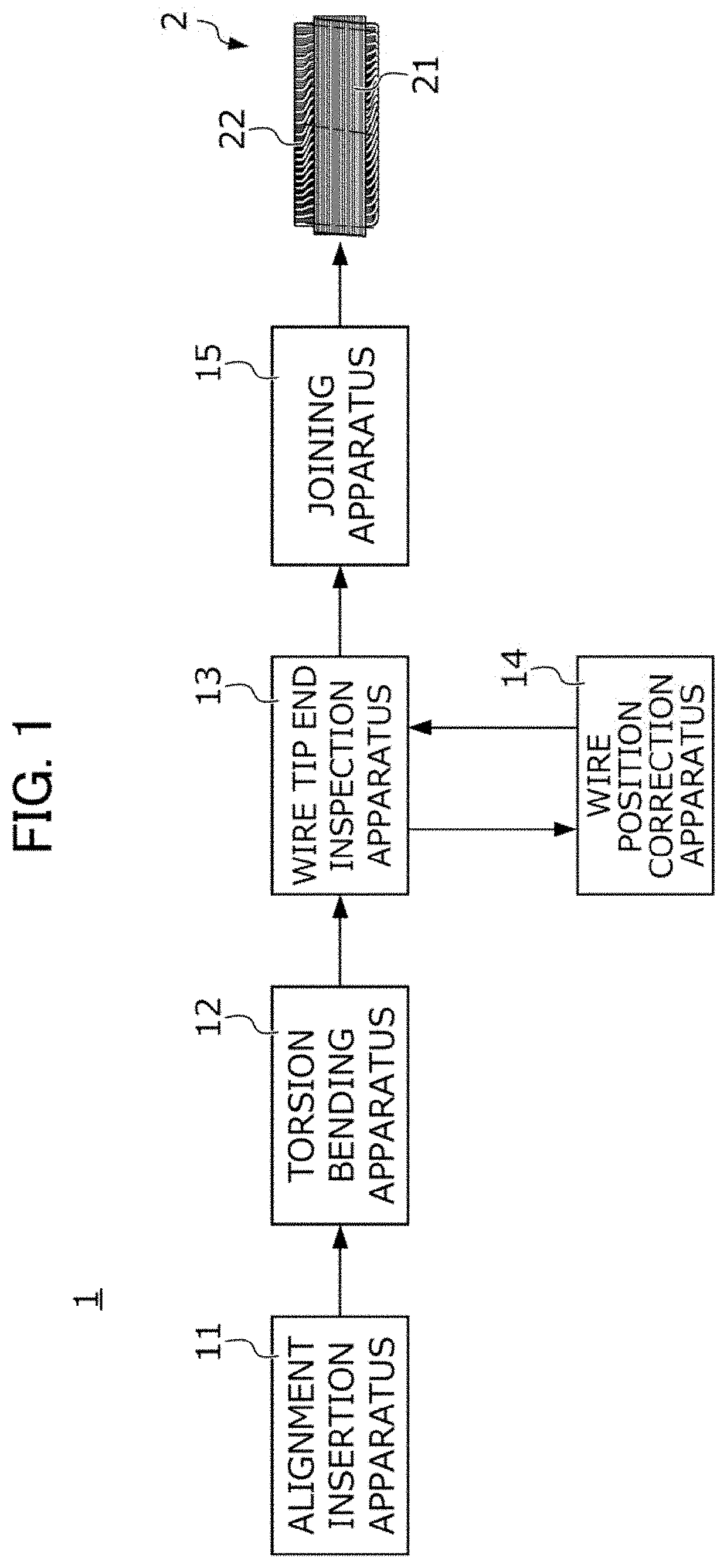
[0046]FIG. 1 is a diagram showing part of an apparatus 1 for manufacturing a stator used for a rotating machine such as an electric motor or an electric generator. The stator manufacturing apparatus 1 includes an alignment insertion apparatus 11, a torsion bending apparatus 12, a wire tip end inspection apparatus 13, a wire position correction apparatus 14, and a joining apparatus 15. A stator 2 including a stator core 21 and a coil 25 is manufactured through processing and inspection by the above-described apparatuses 11 to 15.

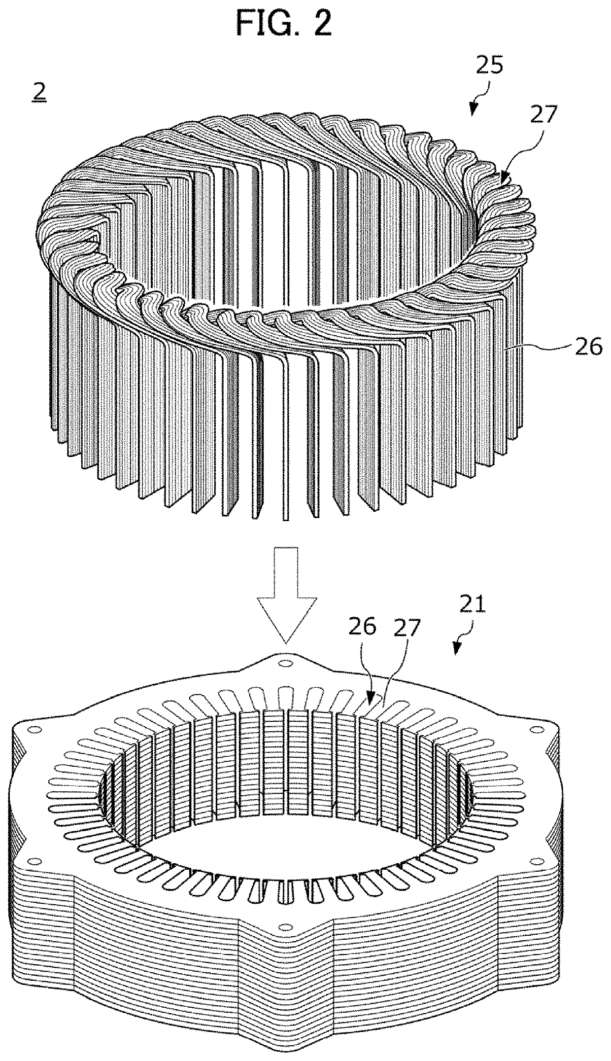
[0047]As shown in FIG. 2, the alignment insertion apparatus 11 attaches the coil 25 prepared in advance to the stator core 21 prepared in advance.

[0048]The stator core 21 is in a hollow circular columnar shape extending a...


PUM

PropertyMeasurementUnit
Widthaaaaaaaaaa
Angleaaaaaaaaaa

Abstract

A wire position correction apparatus 14 corrects, in a stator 2 including an annular stator core 21 formed with a plurality of slots and a plurality of wires arranged in the slots, a tip end position of a wire leg portion 261 of the wire protruding from the slot to a reference position. The wire position correction apparatus 14 includes a wire clamper 4 that holds a tip end portion 263 of the wire leg portion 261, a turning mechanism 5 that supports the wire clamper 4 and turns the wire clamper 4 about a center axis passing through a base point P such that the tip end position moves in a direction approaching the reference position, and a movement mechanism 6 that moves the wire clamper 4 and the turning mechanism 5 along the vertical direction and circumferential and radial directions of the stator core 21.

Description

[0001]This application is based on and claims the benefit of priority from Japanese Patent Application No. 2020-047192, filed on 18 Mar. 2020, the content of which is incorporated herein by reference.BACKGROUND OF THE INVENTIONField of the Invention[0002]The present invention relates to a wire position correction method and a wire position correction apparatus. More specifically, the present invention relates to a wire position correction method and a wire position correction apparatus for a stator including an annular stator core and a plurality of wires arranged in slots formed at the stator core.Related Art[0003]A rotating machine such as an electric motor or an electric generator includes a stator and a rotor. The stator of the rotating machine is manufactured by the following steps, for example.[0004]First, a plurality of wires as electric conductors is formed in a substantially U-shape, thereby producing a plurality of coil elements. Next, the plurality of produced coil elemen...

Claims


Application Information

Patent Timeline
IPC IPC(8): H02K15/06H02K1/16H02K3/12H02K3/48B21F1/00
CPCH02K15/062H02K1/16B21F1/00H02K3/48H02K3/12H02K15/0031H02K15/0037H02K15/085H02K15/0081
Inventor NAKAJIMA, JUNJIONDA, HIDEAKI
Owner HONDA MOTOR CO LTD
Why Eureka
Try Eureka