Agricultural Implement

a technology of agricultural implements and implements, applied in the field of agricultural implements, can solve the problems of more complex and expensive hinge assembly, shock on associated components of implements, etc., and achieve the effects of smooth and gentle transfer of agricultural implements, improved durability, and simple and cost-effective construction

Active Publication Date: 2021-09-30
INC BLUE LEAF I
View PDF0 Cites 0 Cited by
  • Summary
  • Abstract
  • Description
  • Claims
  • Application Information

AI Technical Summary

Benefits of technology

[0005]It is therefore an object of the present invention to provide an agricultural implement having at least one foldable frame member with improved durability, which allows for a simple and cost-efficient construction. It is a further object of the present invention to provide a method for smoothly and gently transferring an agricultural implement into a working condition.
[0017]In this manner, an implement is provided, which allows the foldable second frame member to move relative to the first frame member in the working position, in which the connecting pin is able to move along the slot, and which prevents the second frame member from tipping over during expansion by blocking the pin from moving along the slot. Thus, shocks on the implement's components are prevented and the loads acting on the components are reduced. Furthermore, the actuating assembly comprises only a small number of simple components resulting in a simple and cost-efficient design of the pivotal connection between the first and second frame members.
[0019]Preferably, the first link is directly connected to the first frame member and the second link is directly connected to the second frame member to further simplify the design of the actuating assembly. The third link may be directly and fixedly attached to the actuator. For example, the third link is fixedly attached to a piston rod of a cylinder. Being “directly” connected or attached to an element shall define a connection only comprising connecting means, such as a bolt, but not comprising further elements, such as an additional link member, between the elements directly connected to each other. Therefore, the actuating assembly preferably consists of the actuator, the first link, the second link and the third link as well as suitable connecting means providing the respective pivotal connection.
[0024]Preferably, the first actuating assembly is configured to be in positive control of the second frame member while moving the second frame member between the retracted position and the expanded position and vice versa. That is, the second frame member does not have any freedom to move independently, in particular, in an intermediate range of motion in which the center of gravity of the second frame member moves beyond the first pivot axis in the lateral direction. Rather, between the retracted position and the expanded position, the second frame member is constantly guided and held by the actuating assembly and is therefore not freely movable with respect to the first frame member. Tipping over of the second frame member can therefore be avoided reliably in both directions of movement.
[0049]releasing the one of the first link, the second link and the third link comprising the slot, thereby enabling translatory motion of the third link with respect to the connecting pin, when the second frame member is arranged in the expanded position.
[0050]Preferably, the third link is prevented from translatory motion by means of the second and third links and the third link is released by the second link.

Problems solved by technology

This, however, often results in the adverse effect of the foldable frame member tending to tip over from one side to the other when its center of gravity moves beyond the pivot axis in the lateral direction, thereby generating a shock on associated components of the implement every time the foldable frame member is folded in or folded out.
Thus, additional means for absorbing said shock have to be provided or the pivotable hinge connection must be designed to avoid tipping over of the foldable frame member resulting in a more complex and expensive hinge assembly.

Method used


Image

  • Agricultural Implement
  • Agricultural Implement
  • Agricultural Implement

Examples


Embodiment Construction

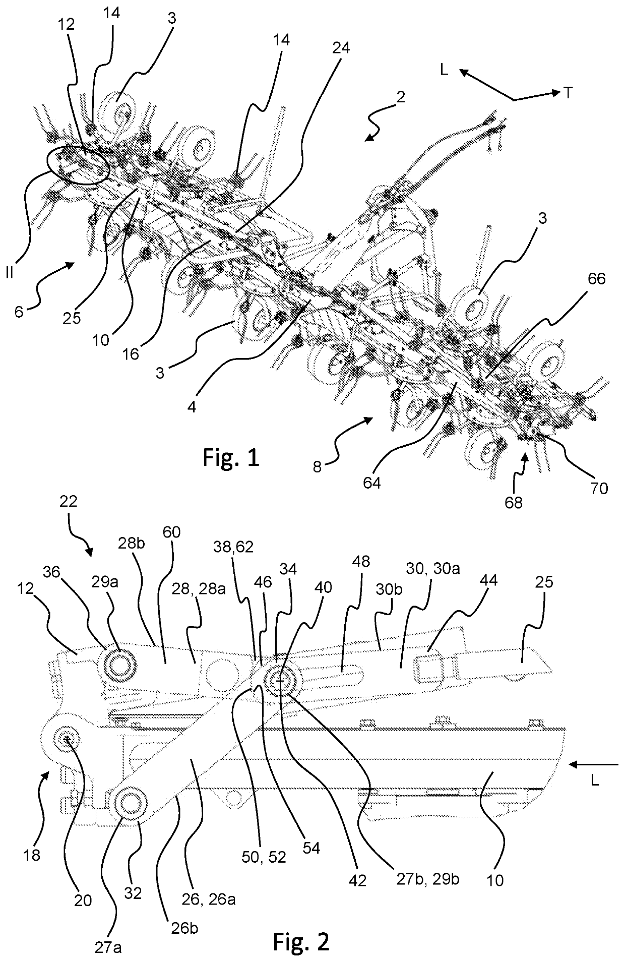
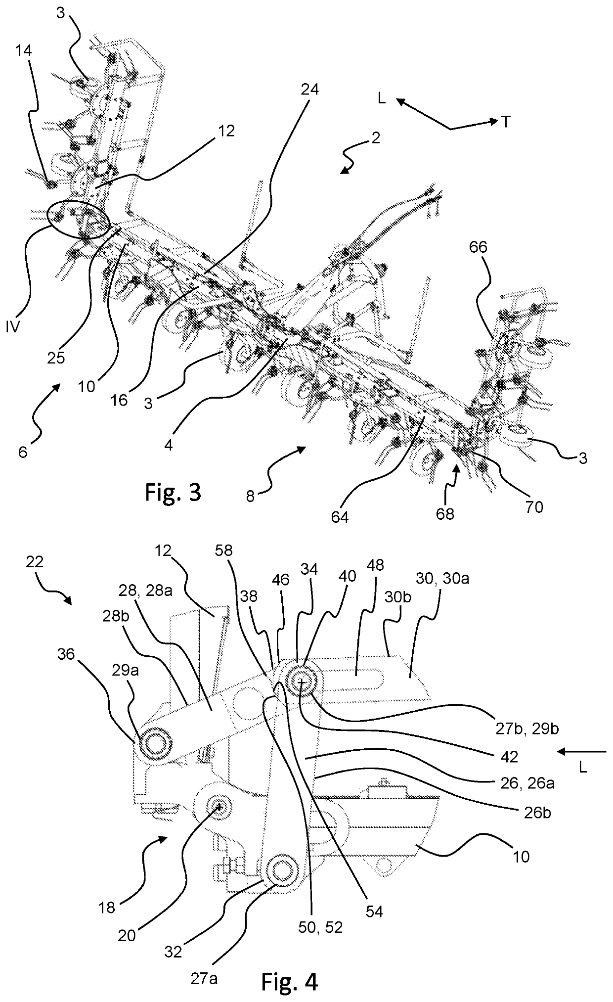
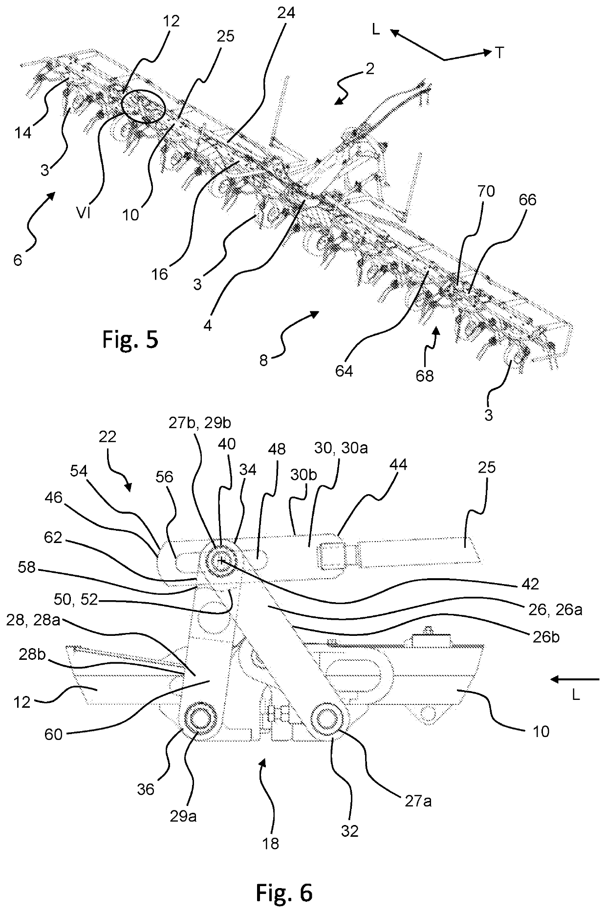
[0059]In FIGS. 1, 3 and 5 and agricultural implement 2 according to the invention is shown in different conditions. In the embodiment shown in FIGS. 1 to 6, the implement 2 is a tedder having multiple ground engaging wheels 3 to support the implement 2 on the ground and multiple rotors forming implement tools 14. It will be apparent from the description of the implement 2 below, however, that the invention is not limited to a tedder but may be applied to any agricultural implement 2 having foldable frame members.

[0060]The implement 2 comprises a central main frame 4 towable by an agricultural vehicle, such as a tractor. The implement 2 is movable in a travel direction indicated by arrow T in FIG. 1. The implement 2 further comprises wing-like frame assemblies 6, 8 pivotally connected to opposite sides of the main frame 4 in a lateral direction L of the implement 2, the lateral direction L extending transverse to the travel direction T. The wing-like frame assemblies 6, 8 can be rota...


PUM


Abstract

An agricultural implement includes a first frame member and a second frame member pivotally connected to each other and an actuating assembly configured to rotate the second frame member. The actuating assembly includes a first link pivotally connected to the first frame member, a second link pivotally connected to the second frame member, and a third link attached to an actuator. Two of the first, second, and third links are pivotally connected by a connecting pin, which is received in a slot formed in the third one of the links. The actuating assembly is configured to prevent the pin from moving along the slot and to allow rotation of the second link relative to the third link, when the second frame member is arranged between a retracted position and an expanded position, and to allow the pin to move along the slot, when the second frame member is arranged in the expanded position.

Description

FIELD OF THE INVENTION[0001]The present invention relates to an agricultural implement and a method for transferring an agricultural implement into a working condition.[0002]In particular, the present invention relates to an agricultural implement having a central main frame and at least one foldable frame member pivotally arranged on one side of the main frame in a lateral direction of the implement, such as a tedder, a plow, a seeder or the like requiring the at least one foldable frame member to follow the ground surface while moving the implement across a field.BACKGROUND OF THE INVENTION[0003]To allow the implement to travel on a road, implements are transferred into a transport condition, in which their width in a lateral direction of the implement is small enough for road traffic and does not exceed a given limit. When arriving on the field, the implements are then transferred into a working condition, in which the at least one foldable frame member carrying at least one tool...

Claims


Application Information

Patent Timeline
Patent Type & Authority Applications(United States)
IPC IPC(8): A01D78/10
CPCA01D78/1014A01B73/044A01D78/1078
Inventor VAN DER LELIJ, BART
Owner INC BLUE LEAF I
Why Eureka
Try Eureka