
Pressure booster

Active Publication Date: 2021-09-30
SMC CORP
View PDF9 Cites 2 Cited by
  • Summary
  • Abstract
  • Description
  • Claims
  • Application Information

AI Technical Summary

Benefits of technology

The present invention provides a pressure booster that improves tank filling efficiency and reduces pressurized fluid consumption. The booster includes a path for directly supplying fluid to the tank, which saves time and reduces fluid waste.

Problems solved by technology

However, when filling the tank with air from atmospheric pressure, it takes a long time to fill the tank, especially when the pressure booster is small.

Method used


Image

  • Pressure booster
  • Pressure booster
  • Pressure booster

Examples


Embodiment Construction

[0021]Hereinafter, a preferable embodiment of a pressure booster according to the present invention will be described in detail with reference to the accompanying drawings.

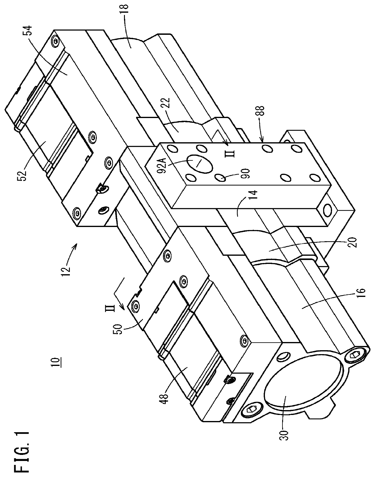
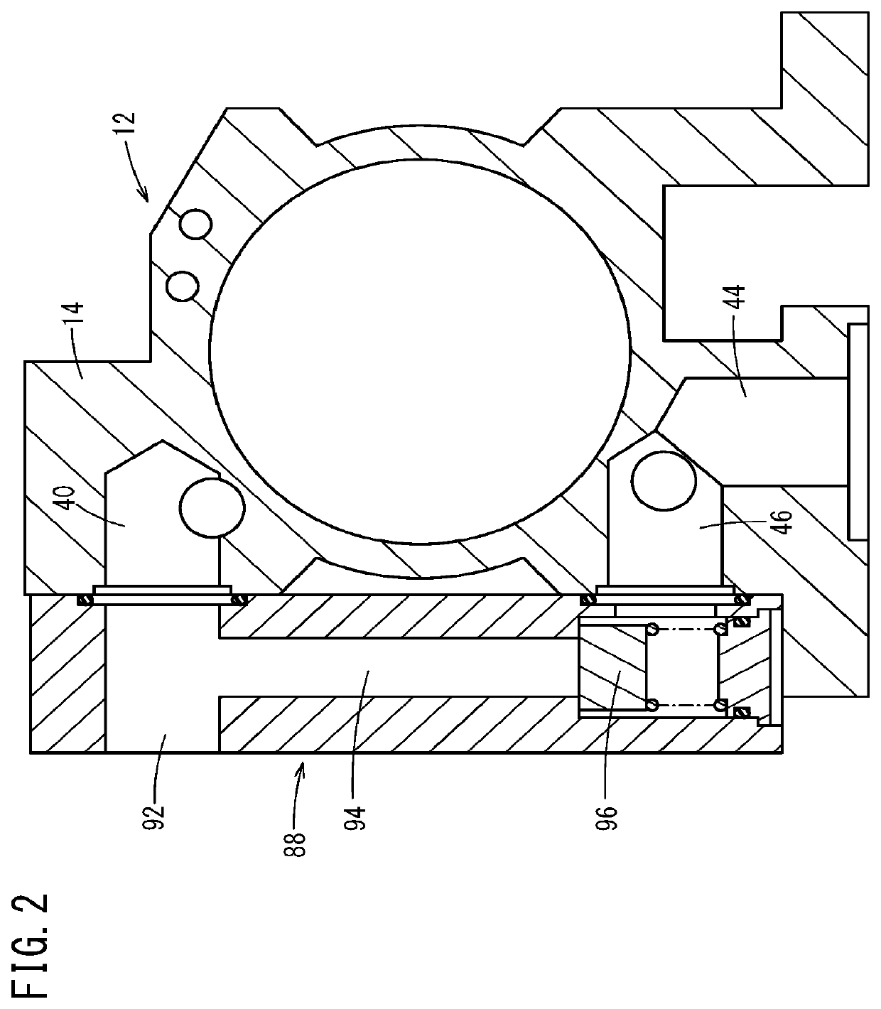
[0022]As shown in FIGS. 1 and 2, a pressure booster 10 of the present invention is composed of a pressure boosting unit 12 and a bypass unit 88, and is arranged between a fluid supply source (compressor) and a tank. The fluid supply source and tank are not illustrated.

(Configuration of Pressure Boosting Unit 12)

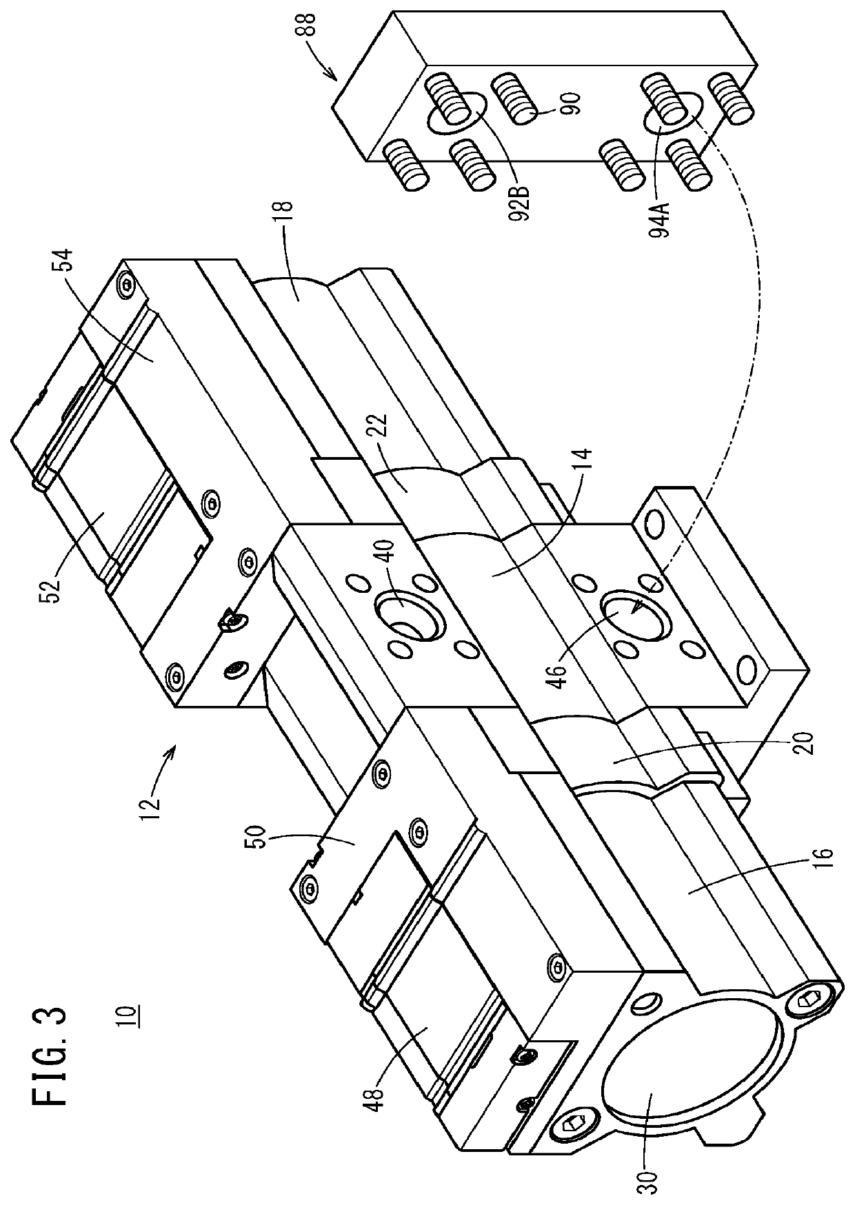
[0023]As shown in FIG. 3, the pressure boosting unit 12 has a triple cylinder structure in which a first drive cylinder 16 and a second drive cylinder 18 are joined to a first end side (one end side) and a second end side (the other end side) of the pressure boosting cylinder 14, respectively. A first cover member 20 is interposed between the first drive cylinder 16 and the pressure boosting cylinder 14, and a second cover member 22 is interposed between the pressure boosting cylinder 14 and the second driv...


PUM


Abstract

A pressure booster includes a pressure boosting unit and a bypass unit. The pressure boosting unit includes an input port connected to the side of a fluid supply source and an output port connected to the side of a tank. The pressure boosting unit boosts the pressure of a pressurized fluid supplied to the input port and outputs the pressure-boosted pressurized fluid from the output port. The bypass unit includes a bypass flow path having one end connected to the fluid supply source side and the other end connected to the output port side. The bypass flow path is provided with a bypass check valve configured to block the flow of the pressurized fluid from the output port side to the fluid supply source side.

Description

CROSS-REFERENCE TO RELATED APPLICATION[0001]This application is based upon and claims the benefit of priority from Japanese Patent Application No. 2020-053573 filed on Mar. 25, 2020, the contents of which are incorporated herein by reference.BACKGROUND OF THE INVENTIONField of the Invention:[0002]The present invention relates to a pressure booster capable of boosting and outputting a pressurized fluid from a fluid supply source.Description of the Related Art:[0003]Conventionally, there has been known a pressure booster that boosts air with a primary pressure, supplied from a compressor and outputs the air with a predetermined secondary pressure.[0004]As an example of such a pressure booster, Japanese Laid-Open Patent Publication No. 2018-084270 discloses a pressure booster having drive cylinders arranged on both sides of a pressure boosting cylinder. As described in this document, the pressurized fluid output from the pressure booster is usually stored in an external tank and used i...

Claims


Application Information

Patent Timeline
IPC IPC(8): F15B3/00F15B11/032
CPCF15B3/00F15B2211/214F15B2211/7053F15B11/032F04B37/12F04B39/123F04B39/10F15B2211/851F15B2211/8855F15B2211/30505F15B13/027F15B1/26F04B9/129F04B9/133
Inventor TAKAKUWA, YOUJIMONDEN, KENGO
Owner SMC CORP
Learn More