Fuel-cell end plate

Active Publication Date: 2021-09-30
TOYOTA JIDOSHA KK
View PDF0 Cites 0 Cited by
  • Summary
  • Abstract
  • Description
  • Claims
  • Application Information

AI Technical Summary

Benefits of technology

This patent describes a fuel-cell end plate that is used in fuel cell stacks. The end plate has two ribs that intersect with each other, one of which is shorter in height than the other. This design reduces stress on the end plate and improves its performance. The difference in height between the two ribs should not be greater than 4 mm for optimal results. The end plate has a quadrilateral shape and can be strengthened against deformation. The fuel-cell end plate can also have fastening points for attaching the fuel cell stack, and the design of the ribs can further enhance the rigidity of the end plate.

Problems solved by technology

If such a large stress is locally generated, the end plate may become fatigued and decrease in strength.

Method used


Image

  • Fuel-cell end plate
  • Fuel-cell end plate
  • Fuel-cell end plate

Examples


Embodiment Construction

A. Overall Configuration of Fuel Cell

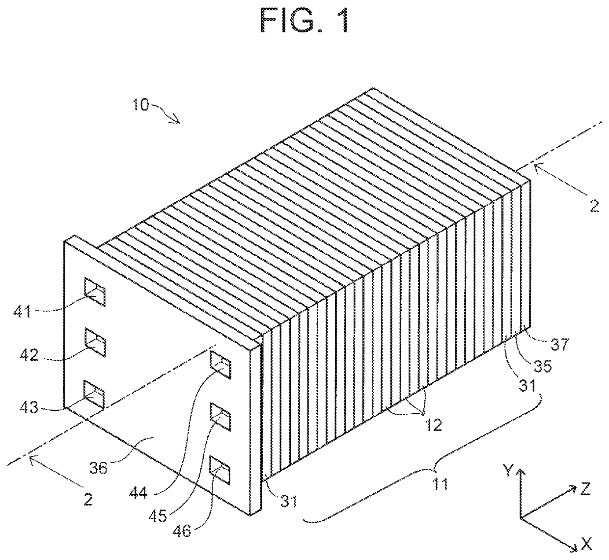
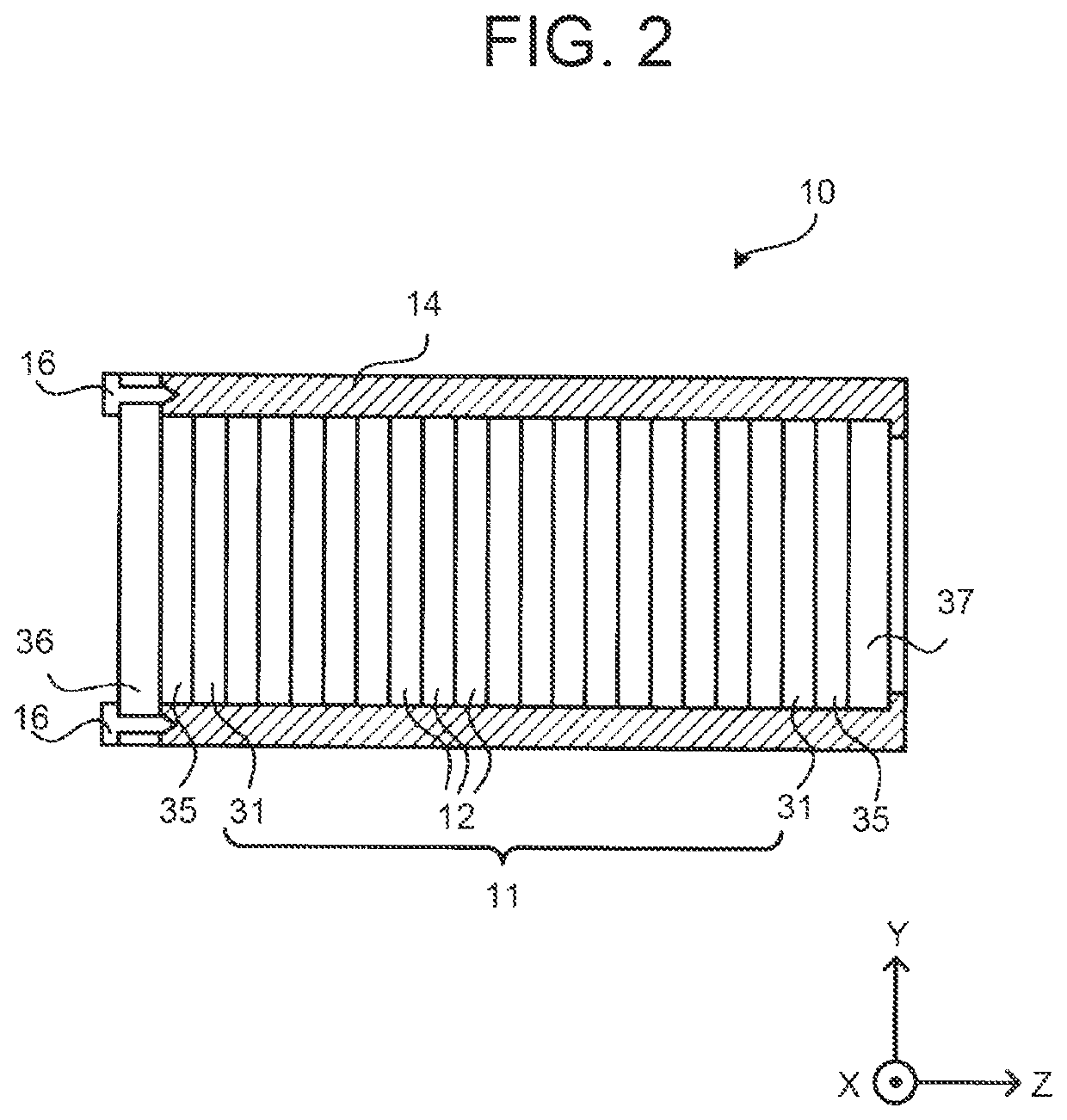
[0021]FIG. 1 is a perspective view showing an external appearance of a fuel cell stack 10 as one embodiment of this disclosure, and FIG. 2 is a schematic sectional view showing a general configuration of the fuel cell stack 10. In FIG. 1, the position of the section of FIG. 2 is indicated as section 2-2. In FIG. 1 and FIG. 2, and FIG. 3 and FIG. 4 to be described later, X, Y, and Z-axes that are orthogonal to one another are indicated to show the correspondence relationship among the drawings. The fuel cell stack 10 can be installed in a moving body, such as a vehicle, and used as a driving power source of the moving body. Alternatively, the fuel cell stack 10 may be used as a stationary power source.

[0022]The fuel cell stack 10 includes: a stack 11 formed by stacking a plurality of single cells 12; a pair of terminal plates 31; a pair of insulating plates (insulators) 35; and a pair of end plates 36, 37. In the fuel cell stack 10, the end plate ...


PUM


Abstract

Provided is a fuel-cell end plate that is disposed at an end, in a stacking direction, of a fuel cell stack formed by stacking members including a single cell. This fuel-cell end plate has, on a surface disposed so as to face the outside of the fuel cell stack, a first rib that extends in a first direction and a second rib that extends in a second direction different from the first direction, intersects the first rib, and is formed so as to be shorter in height than the first rib.

Description

CROSS-REFERENCE TO RELATED APPLICATION[0001]This application claims priority to Japanese Patent Application No. 2020-052524 filed on Mar. 24, 2020, incorporated herein by reference in its entirety.BACKGROUND1. Technical Field[0002]This disclosure relates to a fuel-cell end plate.2. Description of Related Art[0003]There is a known configuration of a fuel-cell end plate in which, to enhance the strength thereof, pluralities of reinforcing ribs extending in a horizontal direction and a vertical direction (longitudinal and lateral directions) are provided in a lattice pattern on an outer surface of the fuel-cell end plate. (See, e.g., Japanese Patent Application Publication No. 2015-032421.)SUMMARY[0004]The inventors of the present application have found that when ribs extending in the longitudinal and lateral directions are provided in a lattice pattern as described above, an undesirably large stress can be locally generated near a portion at which a rib extending in the longitudinal d...

Claims


Application Information

Patent Timeline
IPC IPC(8): H01M8/2465
CPCH01M8/2465H01M8/2432H01M8/2475H01M8/248Y02E60/50
Inventor TAKABATAKE, YUMAKATAYAMA, MASAHIRO
Owner TOYOTA JIDOSHA KK
Why Eureka
Try Eureka