Turbomachine rotor blade, turbomachine rotor disc, turbomachine rotor, and gas turbine engine with different root and slot contact face angles

Active Publication Date: 2015-12-17
SIEMENS ENERGY GLOBAL GMBH & CO KG
View PDF23 Cites 0 Cited by
  • Summary
  • Abstract
  • Description
  • Claims
  • Application Information

AI Technical Summary

Benefits of technology

[0076]In idle state, i.e. when the turbomachine rotor stands still and no radial—i.e. centrifugal—forces are exerted on the components such as the root(s) and the slot(s), a gap between the contact face of a root lobe and the contact face of a slot lobe may be present. When the turbomachine rotor starts rotating, the centrifugal force pushes or presses the blade with its root including its root lobes radially outward

Problems solved by technology

However, after a certain lifetime of the root, the root may break due to the stress and the mechanical load, particularly at sections that are in physical contact with the slot surfaces in the rotor disc.
Alternative

Method used


Image

  • Turbomachine rotor blade, turbomachine rotor disc, turbomachine rotor, and gas turbine engine with different root and slot contact face angles
  • Turbomachine rotor blade, turbomachine rotor disc, turbomachine rotor, and gas turbine engine with different root and slot contact face angles
  • Turbomachine rotor blade, turbomachine rotor disc, turbomachine rotor, and gas turbine engine with different root and slot contact face angles

Examples


Embodiment Construction

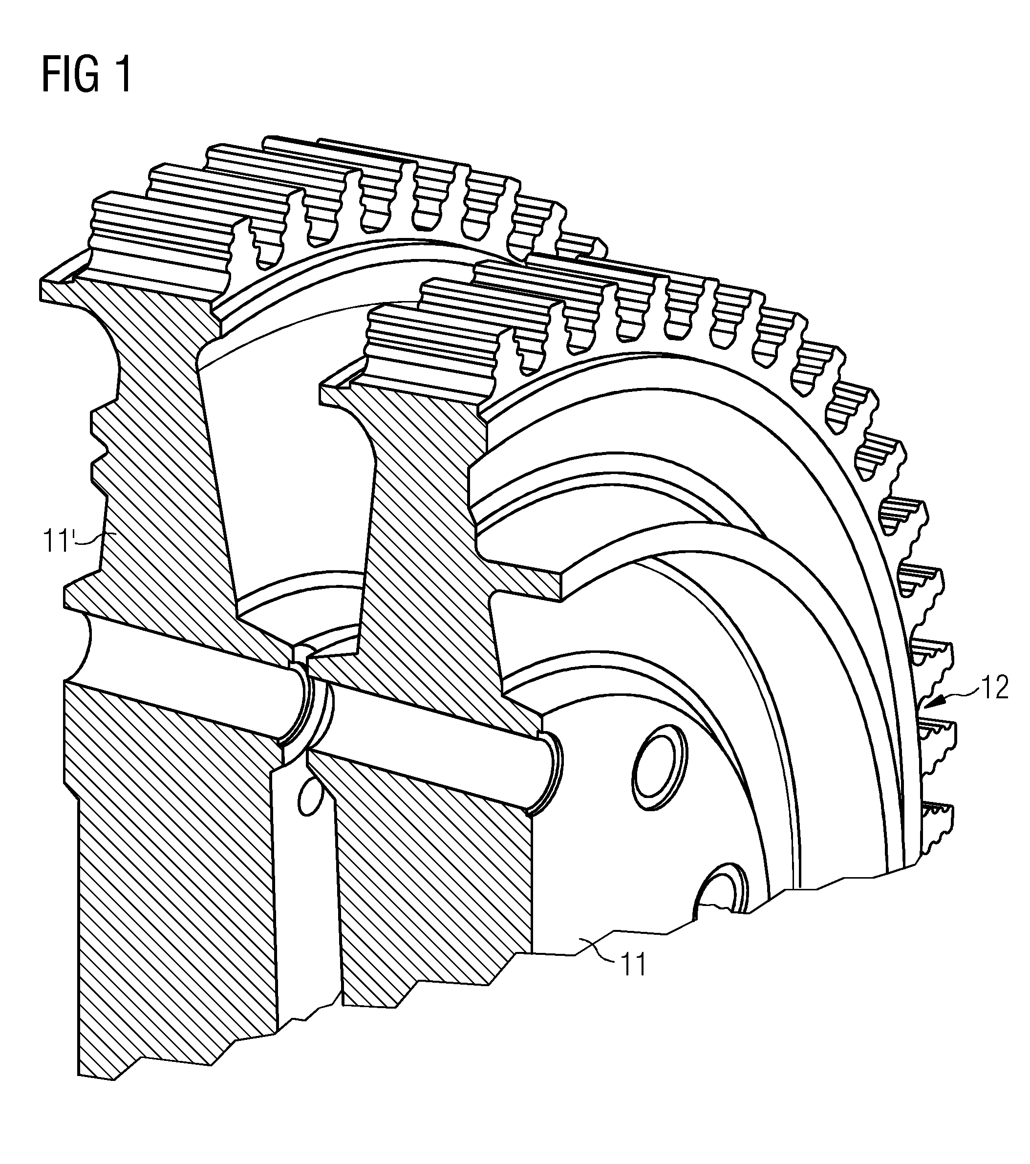
[0086]Referring to FIG. 1, parts of two prior art rotor discs, a rotor disc 11 and a further rotor disc 11′, are shown in a perspective view. At a radially outer region of the disc 11 a plurality of slots 12 are shown. Each firtree shaped slot is designed such that a firtree shaped root (not shown) fits into it.

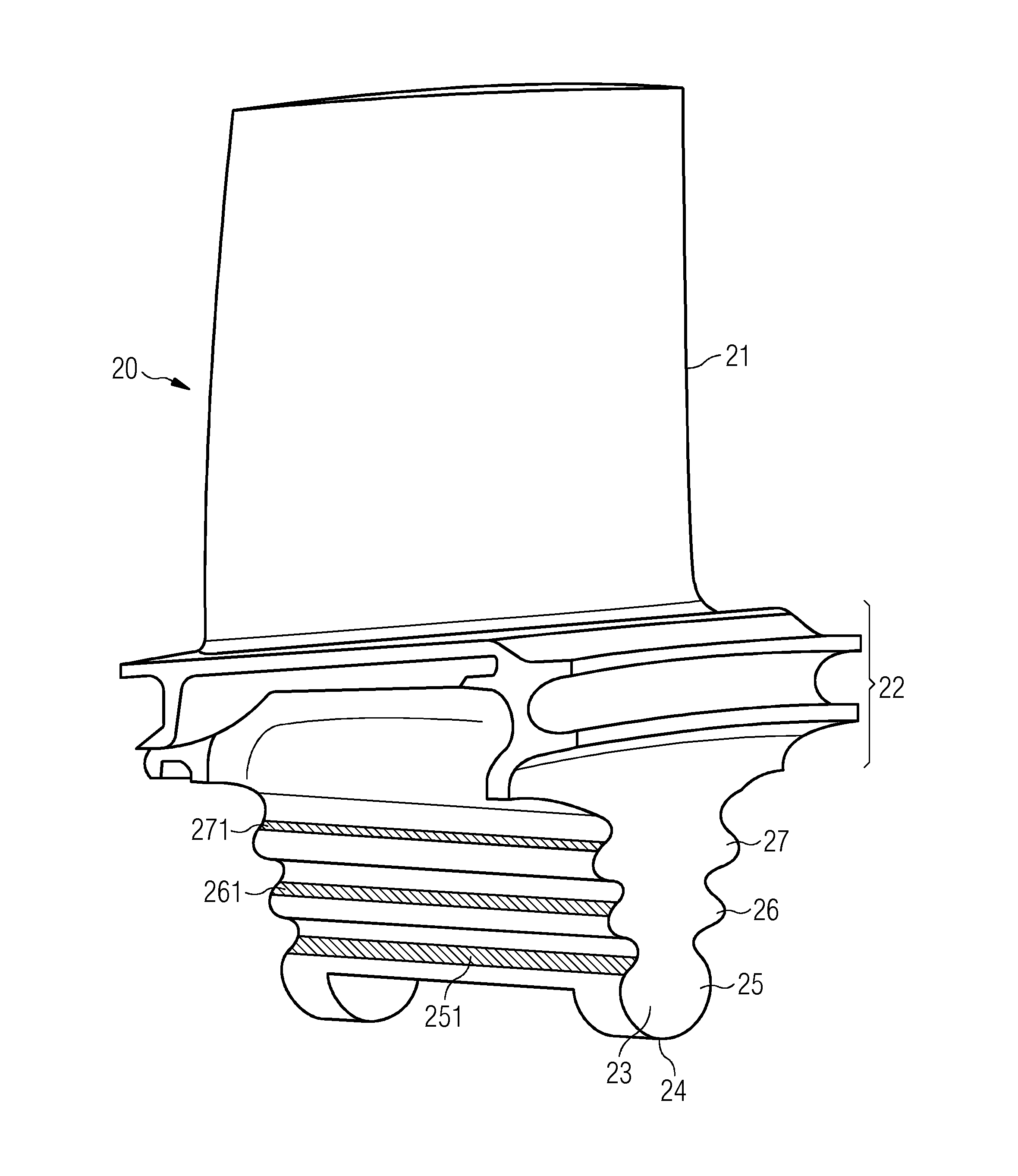
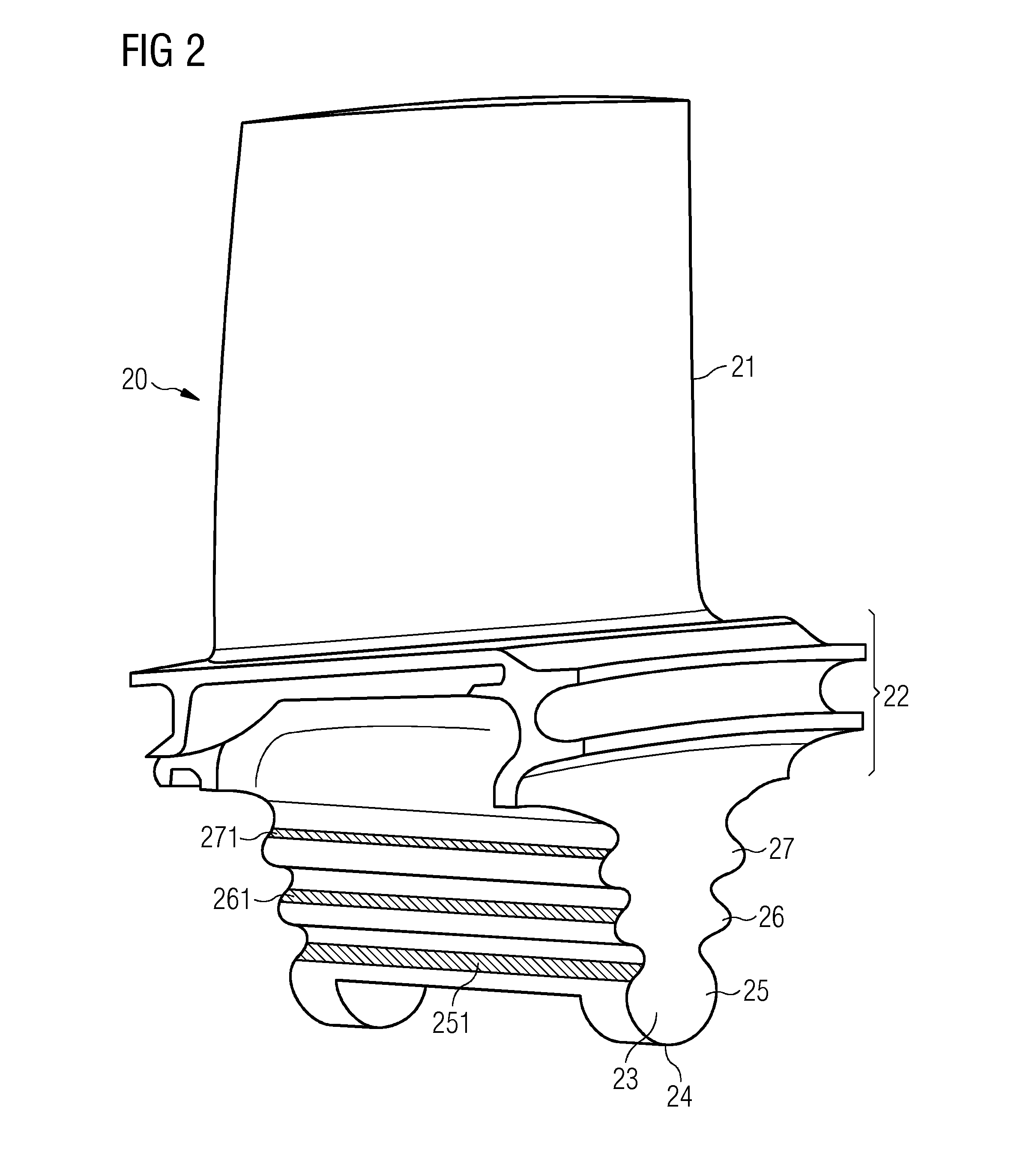
[0087]FIG. 2 shows a prior art blade 20, comprising an aerofoil 21, a platform 22 and a root 23. It should be repeated that the drawings are not to scale: In particular, the aerofoil 21 may be substantially larger in other exemplary embodiments. The root 23 comprises a root bottom 24, a first root lobe 25, a second root lobe 26 and a third root lobe 27. Each root lobe 25, 26, 27 comprises a contact face on its surface section. The first root 25 comprises a first root contact face 251, the second root 26 comprises a second root contact face 261 and the third root 27 comprises a third root contact face 271.

[0088]FIG. 3 depicts parts of a root 23 and a slot 12. This time, a cros...


PUM


Abstract

A turbomachine rotor blade has a firtree shaped root, to be secured in a rotor disc rotatable around a rotor axis. In a plane perpendicular to the rotor axis, the root has a first, second, and third root lobe with a first, second, and third root contact face. Each of the first, second, and third root contact face is angled relative to a radial root bottom axis with a first, second, and third root angle, respectively. The first root angle is smaller than the second and the second root angle is substantially equal to the third. A turbomachine rotor disc has a firtree shaped slot having a first, second, and third slot angle, the first slot angle being smaller than the second and the second slot angle being substantially equal to the third. A gas turbine engine has the turbomachine rotor herein.

Description

CROSS REFERENCE TO RELATED APPLICATIONS[0001]This application is the US National Stage of International Application No. PCT / EP2014 / 051995 filed Feb. 3, 2014, and claims the benefit thereof. The International Application claims the benefit of European Application No. EP13153863 filed Feb. 4, 2013. All of the applications are incorporated by reference herein in their entirety.FIELD OF THE INVENTION[0002]The present invention relates generally to the design of a turbomachine rotor. More specifically, it relates to an improved set of contact face angles of roots of a turbomachine rotor blade and to an improved set of contact face angles of slots of a turbomachine rotor disc.BACKGROUND OF THE INVENTION[0003]A turbomachine rotor typically comprises a plurality of blades, a rotor axis and a rotor disc. A blade typically comprises an aerofoil, a platform and a root. A blade is also called a rotor blade or a rotor blade assembly. The root of the blade is used for joining the blade and the ro...

Claims


Application Information

Patent Timeline
IPC IPC(8): F01D5/30
CPCF01D5/3007F05D2250/314F01D5/02F01D5/30F05D2200/33F05D2250/38
Inventor BLUCK, RICHARDBUTLER, DAVIDOVERTON, DAVID
Owner SIEMENS ENERGY GLOBAL GMBH & CO KG
Why Eureka
Try Eureka