Electronic apparatus

a technology of electronic equipment and electrical components, applied in the field of electronic equipment, can solve the problems of increasing power consumption and the number of connection signals of image pickup elements, inability to communicate stable, and inability to drive the movable unit, so as to reduce electromagnetic field noise and suppress an increase in loads

Active Publication Date: 2021-09-30
CANON KK
View PDF0 Cites 14 Cited by
  • Summary
  • Abstract
  • Description
  • Claims
  • Application Information

AI Technical Summary

Benefits of technology

[0005]The present invention is to provide an electronic apparatus that can reduce electromagnetic field noise while suppressing an increase in loads when a movable member is displaced.

Problems solved by technology

If the flexibility of the flexible substrate is low, the drive of the movable unit may be inhibited.
However, in recent years, the power consumption and the number of connection signals of the image pickup element has tended to increase due to the increase in the number of pixels of moving images and the improvement in functions such as high-speed continuous shooting in the image pickup apparatus.
For this reason, if a flexible substrate formed of a thin layer and provided with a narrow wiring is used to achieve high-speed transmission of more signals, the communication performance may not be stable and cause a radiation source of an electromagnetic field noise (unwanted radiation).
In the conventional method, the flexibility of the flexible substrate may be impaired, and the driving of the movable unit may be inhibited.

Method used


Image

  • Electronic apparatus
  • Electronic apparatus
  • Electronic apparatus

Examples


first embodiment

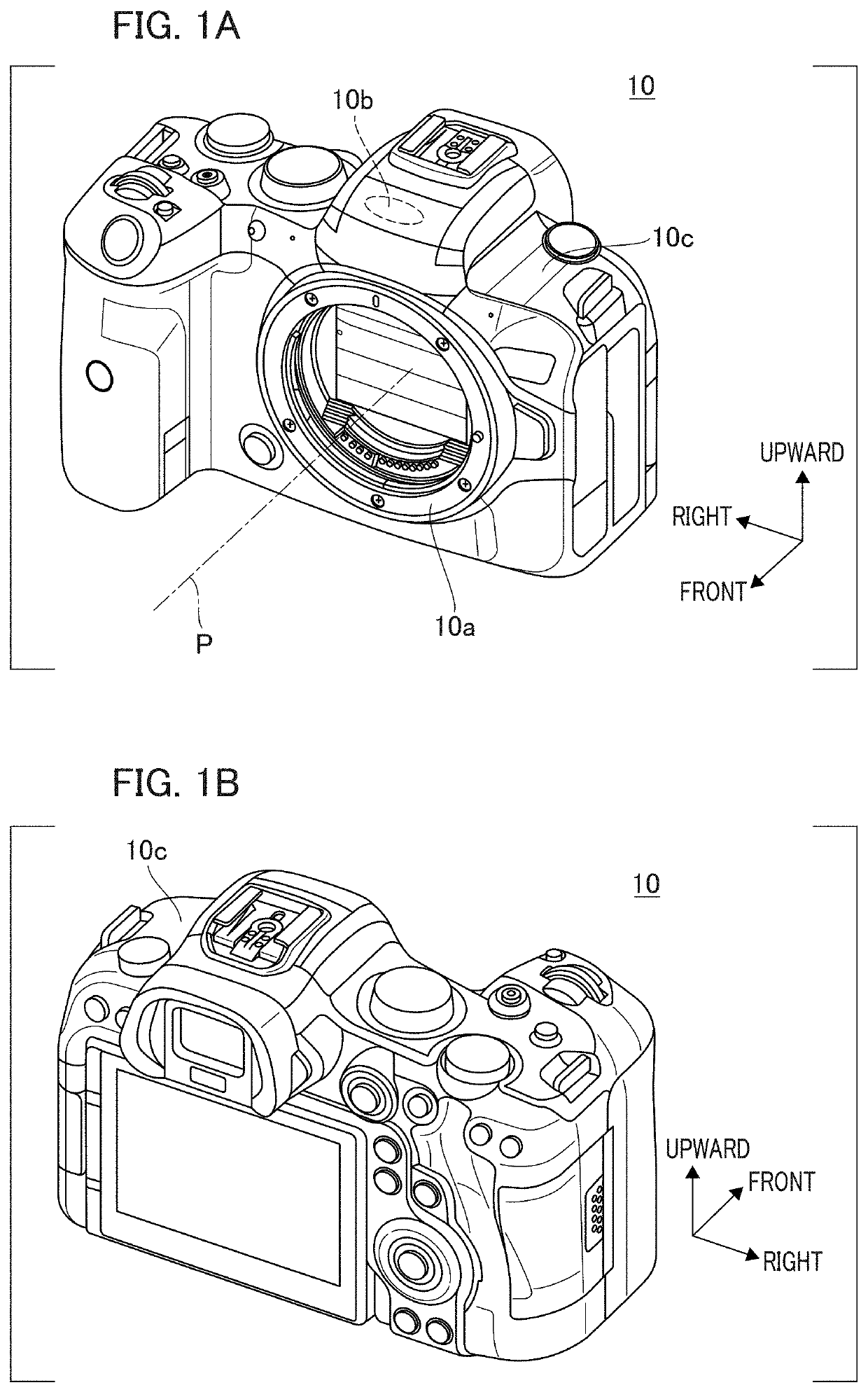
[0024]FIGS. 1A and 1B are perspective views of an image pickup apparatus 10. Regarding the direction of the image pickup apparatus 10, an object side is defined as the front side by using the direction as viewed from a photographer (user) as a reference, and the upward and downward direction, the front-rear direction, and the right and left direction as viewed from the user facing the rear of the image pickup apparatus 10 are respectively defined. Accordingly, FIG. 1A is a perspective view of the image pickup apparatus 10 when viewed from the front and FIG. 1B is a perspective view of the image pickup apparatus 10 when viewed from the rear. In the present embodiment, as an example of an application to an image pickup apparatus, although a lens interchangeable camera in which a lens device can be mounted on a camera body is shown, the present invention is applicable to a camera in which the camera body and the lens unit are integrated.

[0025]The image pickup apparatus 10 is provided w...

second embodiment

[0091]With reference to FIG. 10, FIG. 14, and FIG. 15, the second embodiment of the present invention will be described. In the present embodiment, the difference from the above embodiment will mainly be described with respect to the configuration in which the radio wave absorber 790 is attached to the first flexible substrate 770a. Note that the items that have already been explained are denoted by the reference numerals that have already been used, and the detailed description thereof will be omitted.

[0092]FIG. 14 is an exploded perspective view illustrating the attached position of the electromagnetic field noise countermeasure components on the first flexible substrate 770a in the present embodiment. FIG. 15 is a simplified side view viewed from the right illustrating the state in which the first flexible substrate 770a to which the electromagnetic field noise countermeasure component is attached is connected.

[0093]The first fixing portion 778 and the wiring portion 776 shown in...


PUM


Abstract

An image pickup apparatus includes an image pickup unit and a control unit that controls the unit. The control unit has a control substrate, and the image pickup unit and the control substrate are electrically connected by a flexible substrate. The flexible substrate has a first connection portion connected to the image pickup unit, a wiring portion extending from the first connection portion, and a second connection portion connected to the control substrate. A plurality of curved portions is formed on the flexible substrate, and a sheet-like radio wave absorber is partially fixed to the flexible substrate through a plurality of insulating reinforcing materials.

Description

BACKGROUND OF THE INVENTIONField of the Invention[0001]The present invention relates to an electronic apparatus including a flexible wiring member electrically connected to a movable member.Description of the Related Art[0002]A flexible substrate having flexibility is used for electrical connections in an electronic apparatus. For example, the flexible substrate connects a movable unit (movable member) supported by a fixing unit (support member) in a displaceable state to a control substrate. In an image pickup apparatus having an optical image shake correction function, a movable unit supporting an image pickup element moves in a direction orthogonal to an optical axis with respect to the fixing unit. Japanese Patent Laid-Open No. 2010-192749 discloses an image pickup apparatus in which the drive control of the movable unit is performed by a control substrate while the fixing unit and the movable unit are electrically connected.[0003]A part of a wiring portion of the flexible subst...

Claims


Application Information

Patent Timeline
Patent Type & Authority Applications(United States)
IPC IPC(8): H04N5/225H04N5/232H01Q17/00
CPCH04N5/2253H01Q17/004H04N5/23264H04N5/2257H04N23/52H04N23/54H04N23/6815H04N23/687H04N23/57H04N23/682
Inventor TODA, DAISUKEKAMIYA, JUN
Owner CANON KK
Why Eureka
Try Eureka