
Image processing apparatus, method of controlling the same, image capturing apparatus, and storage medium

a technology of image processing and apparatus, applied in the field of image processing apparatus, to achieve the effect of preventing brightness variation

Active Publication Date: 2021-09-30
CANON KK
View PDF0 Cites 1 Cited by
  • Summary
  • Abstract
  • Description
  • Claims
  • Application Information

AI Technical Summary

Benefits of technology

The present invention is an image processing apparatus that stops images from getting too bright when taken in quick succession with flash emissions. The technical effect of this invention is to reduce the variation in brightness between images.

Problems solved by technology

However, the technique disclosed in Japanese Patent Laid-Open No. 2018-185576 is related to control for relighting w % ben shooting moving images, and control for continuous still image shooting involving flash emission is not particularly considered.

Method used


Image

  • Image processing apparatus, method of controlling the same, image capturing apparatus, and storage medium
  • Image processing apparatus, method of controlling the same, image capturing apparatus, and storage medium
  • Image processing apparatus, method of controlling the same, image capturing apparatus, and storage medium

Examples


first embodiment

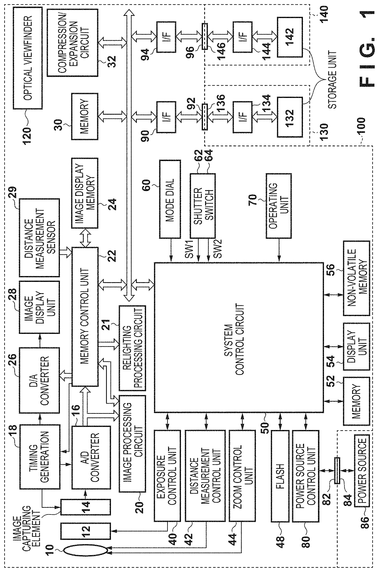
[0020]FIG. 1 is a block diagram illustrating a configuration of an image capturing apparatus 100 according to a first embodiment of the present invention.

[0021]In FIG. 1, the image capturing apparatus 100 comprises a shooting lens 10 as an image capturing unit, a shutter 12 having an aperture function, and an image capturing element 14 for converting optical images to electrical signals. Analog image signals generated by the image capturing element 14 are converted to digital signals by an A / D converter 16.

[0022]A timing generation circuit 18 is controlled by a memory control circuit 22 and a system control circuit 50 and supplies clock signals and control signals to the image capturing element 14, the A / D converter 16, and a D / A converter 26.

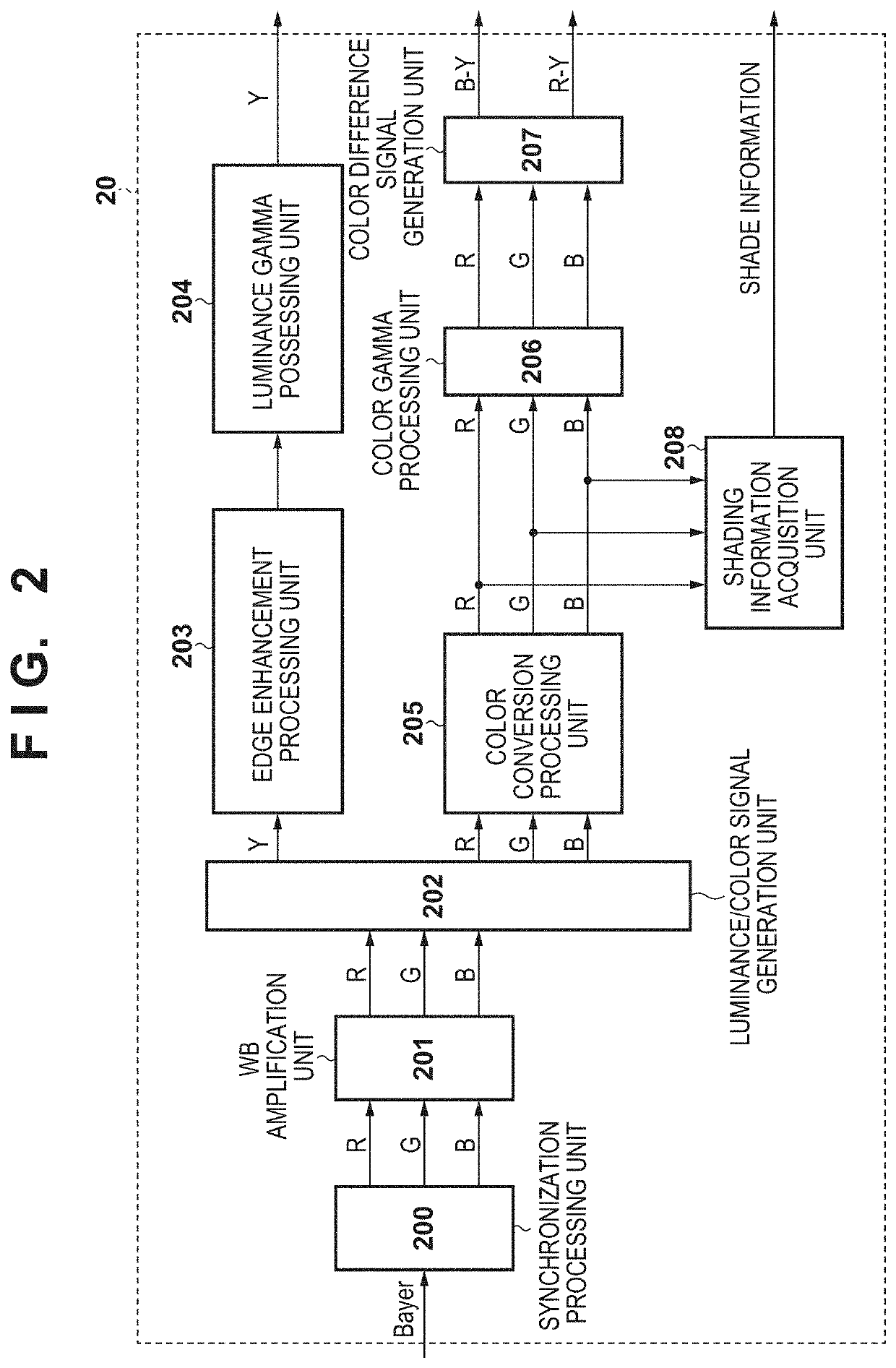
[0023]An image processing circuit 20 performs predetermined pixel interpolation processing or color conversion processing in relation to data from the A / D converter 16 or data from the memory control circuit 22. Also, in the image processing ci...

second embodiment

[0100]Next, a second embodiment of the present invention will be described. Note that the block configuration of the image capturing apparatus of the second embodiment is the same as the image capturing apparatus of the first embodiment illustrated in FIG. 1; therefore, description will be omitted. Hereinafter, description will be given placing the main focus on what is different from the first embodiment.

[0101]In the first embodiment, in step S704, comparison is performed with at least one of the pieces of image data shot continuously before or after the image of interest, the image of interest being an image in which the light emission variation in the flash was detected, and then the virtual light source parameter is set. In contrast to this, in the second embodiment, configuration may be so that a plurality of pieces of image data is used so long as they have been shot continuously.

[0102]FIG. 9 is a view in which images shot by continuous shooting involving flash emission are li...


PUM


Abstract

An image processing apparatus comprises a first acquisition unit configured to acquire an image shot by continuous shooting while emitting a flash; a second acquisition unit configured to acquire light emission information of the flash in the continuous shooting; a detection unit configured to detect a light emission variation of the flash based on the light emission information; a setting unit configured to set a parameter of a virtual light source for correcting a variation of brightness of the image shot by the continuous shooting due to the light emission variation based on a result of detecting the light emission variation; and a correction unit configured to correct the image shot by the continuous shooting based on the set parameter of the virtual light source.

Description

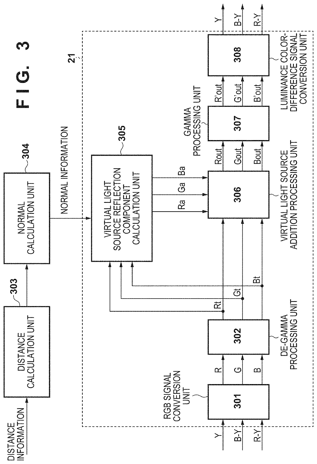
BACKGROUND OF THE INVENTIONField of the Invention[0001]The present invention is related to an image processing apparatus capable of correcting the brightness of an inputted image.Description of the Related Art[0002]Conventionally, a technique called relighting, which is for adjusting the brightness by radiating light from a virtual light source in relation to a subject within a shot image, is known. By appropriately setting parameters of the virtual light source such as the position, intensity, and angle of the virtual light source rather than simply changing the brightness of the entire subject uniformly, a dark region such as a shadow produced by ambient light can be made brighter, and a desired image can be obtained.[0003]In Japanese Patent Laid-Open No. 2018-185576, a technique for setting the parameters of a virtual light source based on information such as the position of a camera, a zoom operation, and a panning operation in order to obtain a desired result of relighting for ...

Claims


Application Information

Patent Timeline
Patent Type & Authority Applications(United States)
IPC IPC(8): H04N5/243H04N5/235G06T7/20H04N23/76
CPCH04N5/243G06T7/20H04N5/2351H04N23/80H04N23/71H04N23/76
Inventor OUCHI, KENJI
Owner CANON KK
Learn More