Inductor component and method for manufacturing same
a technology of inductor components and components, which is applied in the direction of transformers/inductance coils/windings/connections, inductances with magnetic cores, inductances, etc., can solve the problems of unstable welded state of wire members, and achieve stable welded state, simplify the assembling of inductor components, and the effect of stable welded sta
- Summary
- Abstract
- Description
- Claims
- Application Information
AI Technical Summary
Benefits of technology
Problems solved by technology
Method used
Image

Examples
first embodiment
[0044](Configuration of Inductor Component)
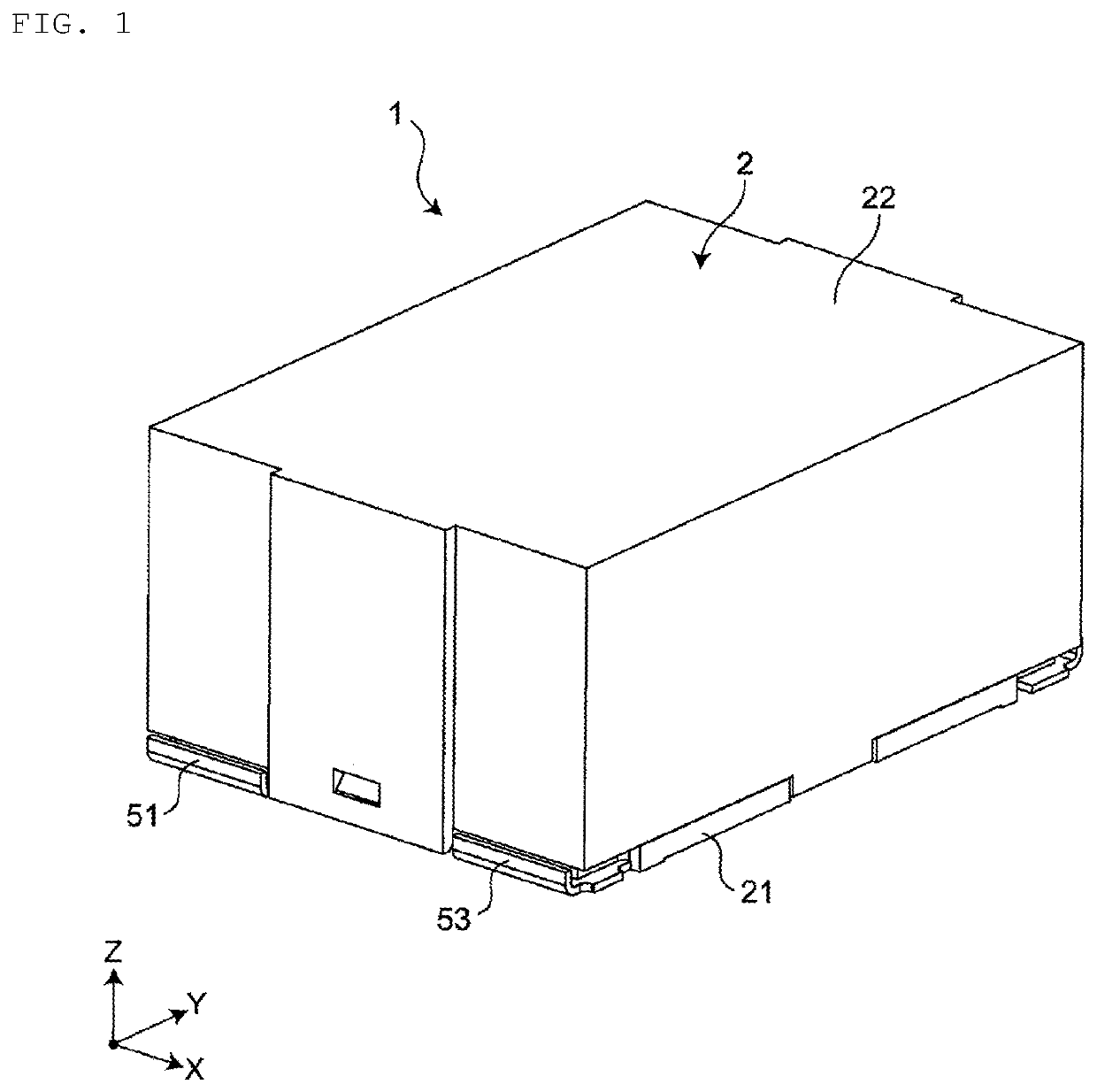
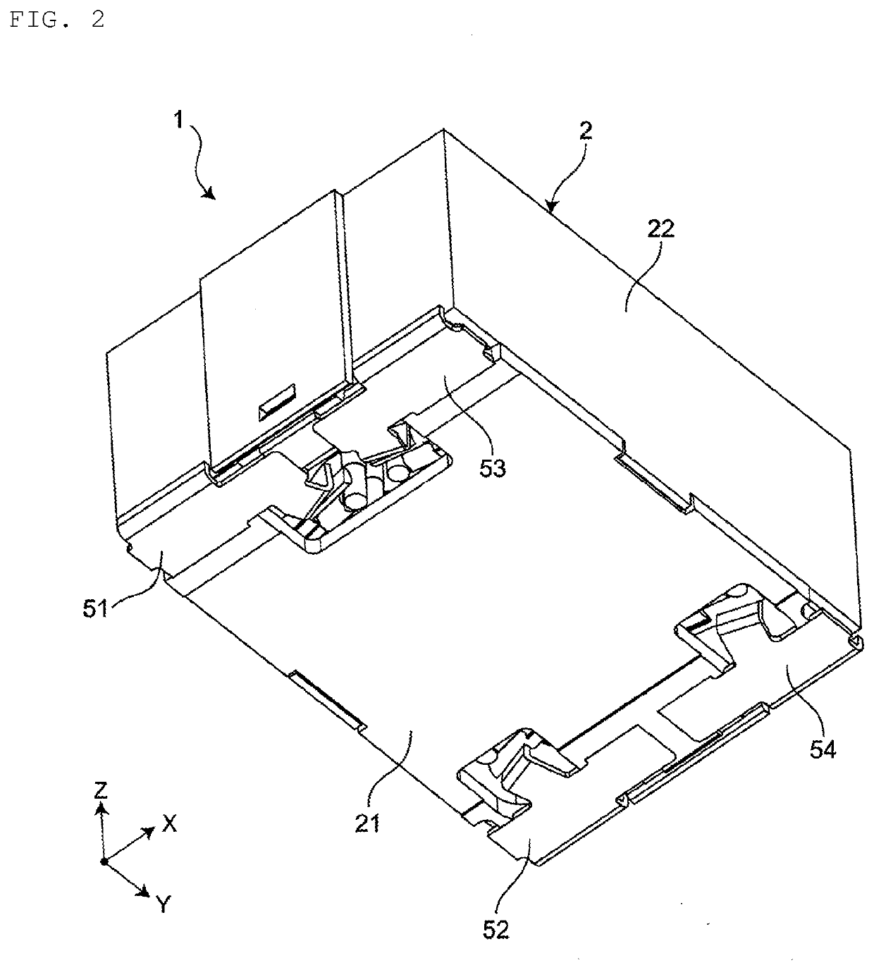
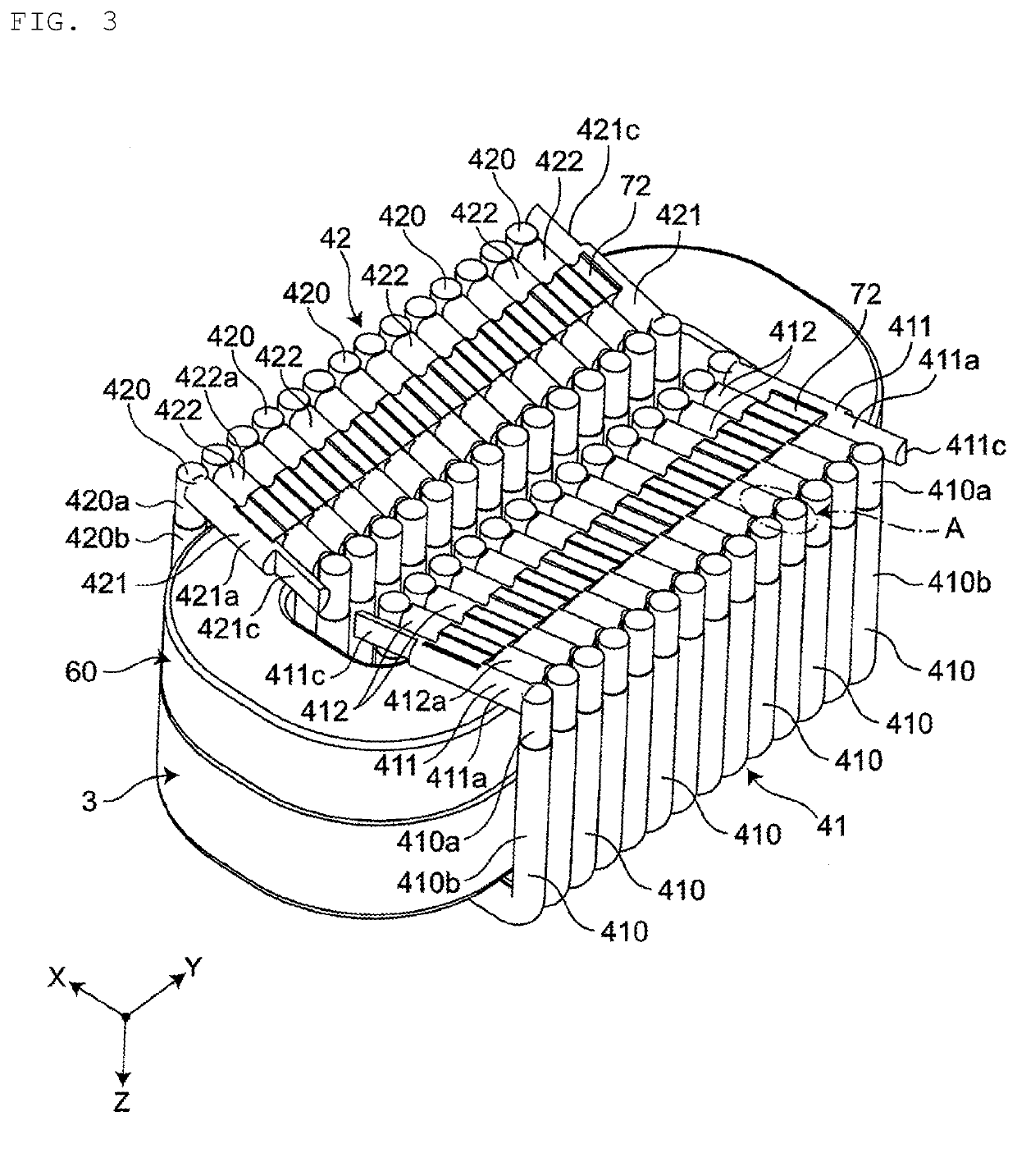
[0045]FIG. 1 is an upper perspective view showing an inductor component according to one embodiment of the present disclosure. FIG. 2 is a lower perspective view of the inductor component. FIG. 3 is a lower perspective view showing the inside of the inductor component. FIG. 4 is an exploded perspective view of the inductor component.
[0046]As shown in FIGS. 1 to 4, an inductor component 1 comprises a case 2, a ring-shaped core 3 housed in the case 2, a first coil 41 and a second coil 42 both wound around the core 3, and a first electrode terminal 51 to a fourth electrode terminal 54 attached to the case 2 and connected to the first coil 41 and the second coil 42. One example of the inductor component 1 is a common mode choke coil.
[0047]The case 2 comprises a bottom plate part 21 and a box-shaped lid part 22 that covers the bottom plate part 21. The case 2 is made from a material having strength and heat resistance, preferably a material havi...
second embodiment
[0118]FIG. 9 is a sectional view showing a second embodiment of the inductor component. The second embodiment is different from the first embodiment in the positions of the connecting members. This different point in the configuration is described hereinbelow. Other points in the configuration are the same as those of the first embodiment and are indicated using the same symbols as those employed in the first embodiment, and the explanation about the same points in the configuration is omitted.
[0119]As shown in FIG. 9, the first connecting member 71 is arranged at positions that respectively face the inner peripheral surface 303 and the outer peripheral surface 304 of the core 3. According to this configuration, the first connecting member 71 is arranged at positions closer to the end parts 410e of the bent pin members 410. Therefore, the positions closer to the end parts 410e of the bent pin members 410 can be fixed by the first connecting member 71, and therefore the misalignment ...
PUM
 Abstract
Description
Claims
Application Information
 - R&D Engineer
- R&D Manager
- IP Professional
- Industry Leading Data Capabilities
- Powerful AI technology
- Patent DNA Extraction
Browse by: Latest US Patents, China's latest patents, Technical Efficacy Thesaurus, Application Domain, Technology Topic.
© 2024 PatSnap. All rights reserved.Legal|Privacy policy|Modern Slavery Act Transparency Statement|Sitemap