
Bone Cutting Guide System for Osteochondral Transplantation

a bone cutting and osteochondral technology, applied in the field of orthopedic medical devices and methods, can solve the problems of less visualization of the entire surface of the acetabulum, and achieve the effects of smooth joint function, restoring the articular surface, and facilitating the precise preparation of both donors

Pending Publication Date: 2021-10-21
JAMALI AMIR A
View PDF4 Cites 0 Cited by
  • Summary
  • Abstract
  • Description
  • Claims
  • Application Information

AI Technical Summary

Benefits of technology

The invention is a device and method for preparing bones for joint replacement. The device includes articular referencing platforms and cutting guides that allow for precise bone shaping and restoration of the joint surface. The device can be used for any joint in the body, such as the knee or hip, and can be adapted for specific procedures. The device facilitates the use of a single or combination of guides for different parts of the joint. The device helps to restore the smooth function of the joint and can be used in revision surgeries or for the preparation of large bone grafts. The method involves using the device to prepare the bone graft and then placing it in the recipient site to restore the joint surface. The device allows for the separation of the graft from the donor bone and the restoration of the natural joint surface. The unique feature of the device is the use of multiple referencing pins to orient the guide at the desired distance from the joint surface. This allows for the harvest of the trochlea with a triangular chevron shape that increases stability after transplantation.

Problems solved by technology

It provides the advantage of easier application to the surface but the disadvantage of less visualization of the entire surface of the acetabulum.

Method used


Image

  • Bone Cutting Guide System for Osteochondral Transplantation
  • Bone Cutting Guide System for Osteochondral Transplantation
  • Bone Cutting Guide System for Osteochondral Transplantation

Examples


embodiment 100

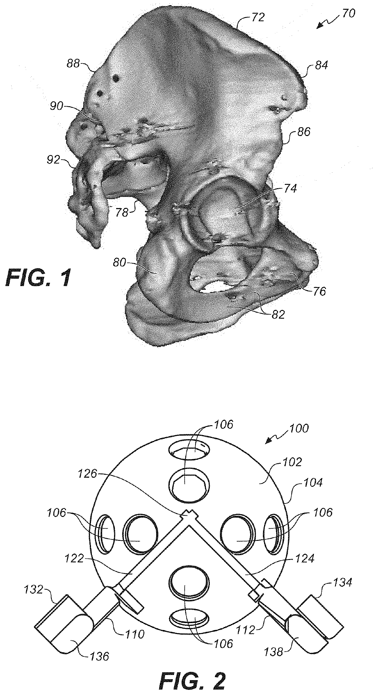
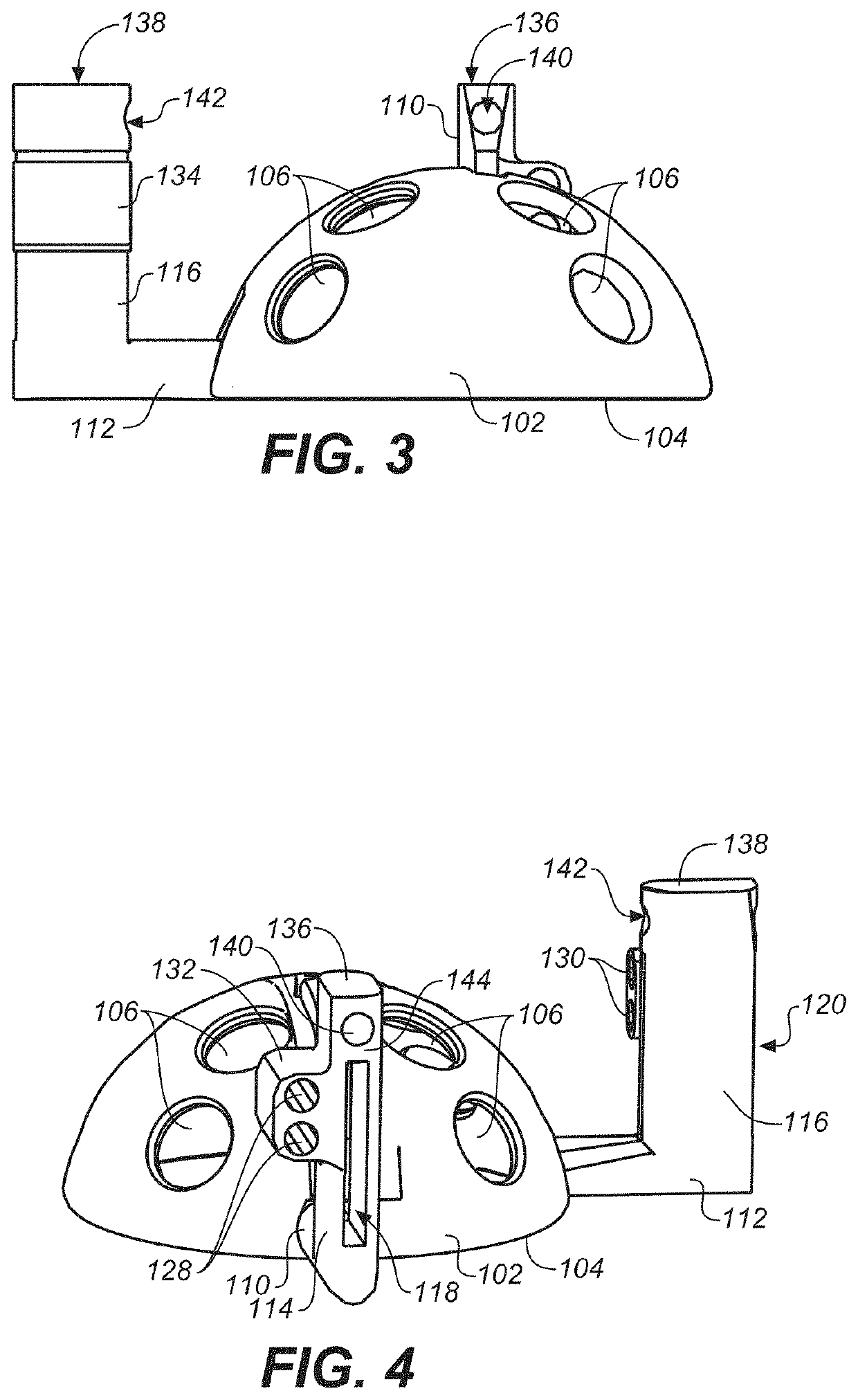
[0077]As seen first in FIGS. 1-13, in an embodiment 100 the bone cutting guide system of the present invention, the modular acetabular cutting tool, can be adapted for use in acetabular transplantation procedures. When so adapted, the device includes a hemispherical reference guide provided in multiple sizes between 40 and 60 mm in 1 mm increments. In the most general terms, the main cutting tool includes a hemispherical body with two vertical cutting slots or channels radially oriented in relation to the perimeter of a lower rim of the hemispherical guide (thus, substantially perpendicular to the widest perimeter of the hemispherical guide). These two cutting channels can be angled between 30 and 150 degrees from one another, with an ideal angle of 90 degrees. The channels extend to and through two outriggers, which each include a vertically oriented body with a vertically oriented cutting slot aligned with one of the cutting channels or slots in the hemispherical body. At the top ...

embodiment 200

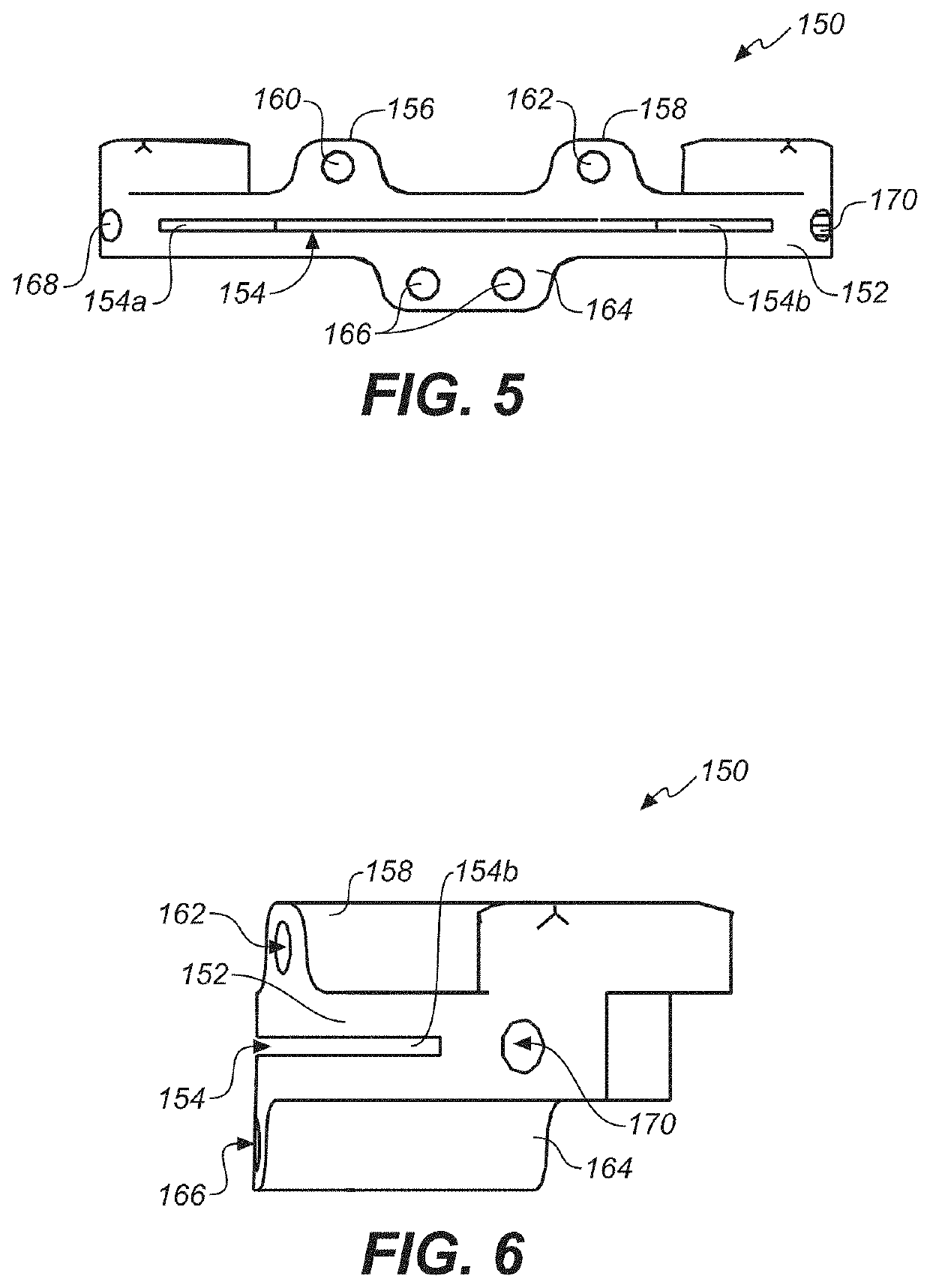
[0085]In another embodiment 200, the monoblock acetabular cutting guide shown in FIGS. 14-19—this embodiment again adapted for use in acetabular transplant procedures—the device includes a unitary (one-piece) cutting tool with both an axial cutting slot and vertical cutting slots so as to provide cutting guides of the kind described in connection with the embodiment of FIGS. 2-13, and thus a device that facilitates the removal of osteochondral grafts from the acetabulum.

[0086]This embodiment 200 of the inventive cutting tool includes a concave surface which approximately matches the edge of the acetabulum and a convex hemispherical central extension that matches the contour of the acetabulum. By resting the vertical portion of this concave complementary surface against the rim of the acetabulum, the guide is set in its position in the horizontal plane. By placing the horizontal portion of this concave surface and its central extension against the rim and the surface of the acetabulu...


PUM


Abstract

A bone cutting guide for preparing both donor and recipient bone, including one or more articular referencing platforms contoured to a bony surface to be prepared, fixation structure to secure the articular referencing platforms on an articular surface, cutting slots spaced apart from the articular referencing platforms at predetermined distances configured to allow the passage of a saw blade in such a way to remove a bone segment either from an allograft donor or from a graft recipient in such a way that both the removed donor and recipient grafts are of the same exact dimensions, whereby when the allograft is placed in the recipient site of the patient's joint, it completely restores the articular surface to the desired level with healthy articular cartilage from the donor.

Description

CROSS REFERENCES TO RELATED APPLICATIONS[0001]The present application is a divisional application of Ser. No. 16 / 136,111, filed Sep. 19, 2018, which is a continuation-in-part of U.S. patent application Ser. No. 14 / 673,636 (Pat. App. Publ. No. 2015-0272594-A1), filed Mar. 30, 2015, which is incorporated in its entirety by reference herein, and which in turn claims the benefit of the priority date of U.S. Provisional Patent Application Ser. No. 61 / 972,376, filed Mar. 30, 2014, which application is also incorporated in its entirety by reference herein.STATEMENT REGARDING FEDERALLY SPONSORED RESEARCH OR DEVELOPMENT[0002]Not applicable.THE NAMES OR PARTIES TO A JOINT RESEARCH AGREEMENT[0003]Not applicable.INCORPORATION BY REFERENCE OF MATERIAL SUBMITTED ON A COMPACT DISC[0004]Not applicable.SEQUENCE LISTING[0005]Not applicable.BACKGROUND OF THE INVENTIONField of the Invention[0006]The present invention relates generally to orthopedic medical devices and methods, and more particularly to ...

Claims


Application Information

Patent Timeline
Patent Type & Authority Applications(United States)
IPC IPC(8): A61B17/15
CPCA61B17/15A61B17/1635A61B17/155A61B17/1746A61B17/1764
Inventor JAMALI, AMIR A.
Owner JAMALI AMIR A
Learn More