Forward fusion system and method for advanced driving assistance

A technology of driving assistance and fusion method, which is applied in the field of ADAS, can solve the problems of large delay, network quality dependence, and no sensor target detection information fusion, etc., to achieve small delay time, enhanced accuracy, stable and smooth target output Effect

Active Publication Date: 2020-09-08
HUAYU AUTOMOTIVE SYST
View PDF15 Cites 8 Cited by
  • Summary
  • Abstract
  • Description
  • Claims
  • Application Information

AI Technical Summary

Problems solved by technology

The above intelligent vehicle map fusion system and method based on roadside equipment builds a real-time map model through the information fusion of the vehicle and the roadside unit, but the above information fusion strategy is unified, and there is no corresponding adjustment according to different ADAS functions. The fusion of map information, without sensor fusion of target detection information, cannot effectively eliminate the target detection error caused by a single sensor
[0006] The active collision avoidance system and method disclosed in the patent document with the application number 201810818601.1 also integrates vehicle information and roadside information through the intelligent vehicle terminal. The smart terminal transmits the result of the fusion information to the roadside unit through 5G, and the roadside unit uploads it to the cloud to realize the function of driving active collision avoidance (AEB), and then sends the alarm and control request back to the vehicle terminal. Four stages: (1) Send the information from the roadside unit to the car; (2) Send the fusion result from the car to the roadside unit; (3) Send the fusion information from the roadside unit to the cloud; (4) The control information after the function is realized in the cloud is transmitted back to the vehicle end. This method will cause a large delay in the transmission of too much information through the network, and it is highly dependent on the quality of the network.

Method used


Image

  • Forward fusion system and method for advanced driving assistance
  • Forward fusion system and method for advanced driving assistance
  • Forward fusion system and method for advanced driving assistance

Examples


Embodiment Construction

[0043] The present invention will be further described below in conjunction with specific embodiments. It should be understood that the following examples are only used to illustrate the present invention but not to limit the scope of the present invention.

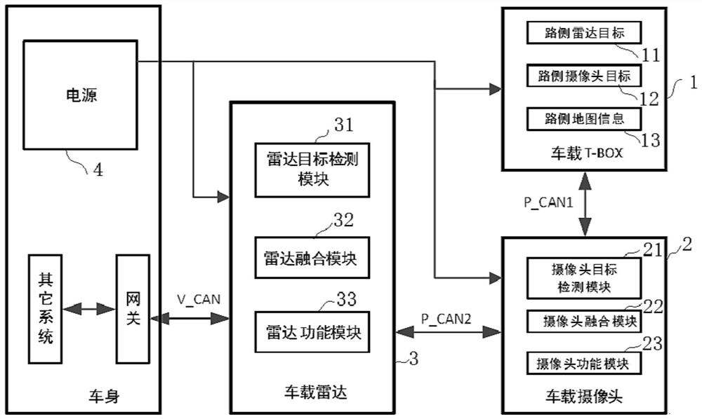
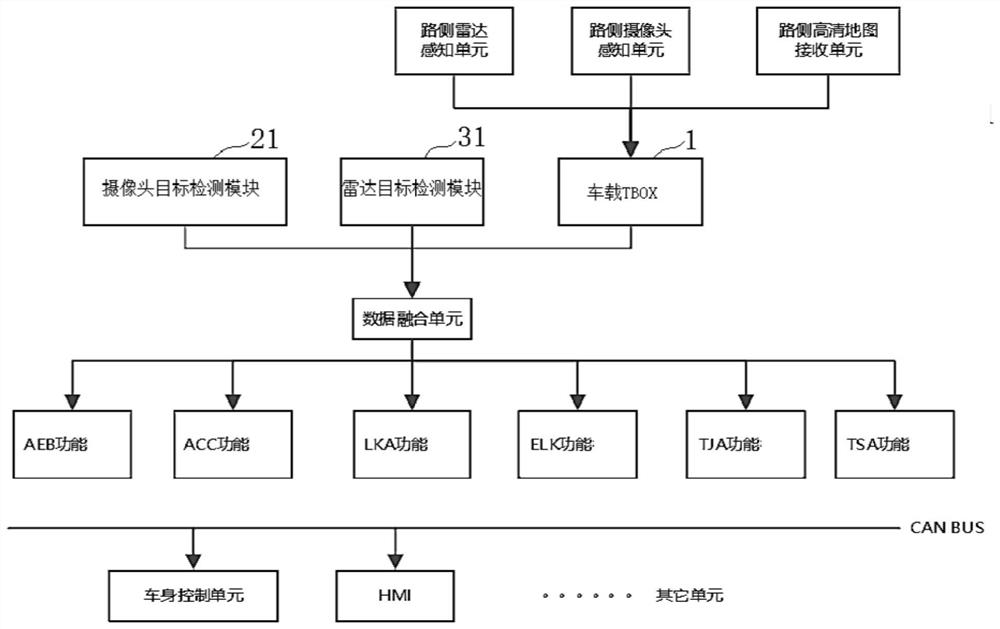
[0044] Such as Figure 1-Figure 2 Shown is a forward fusion system for advanced driver assistance according to one embodiment of the present invention. The forward fusion system of the advanced driving assistance includes a vehicle-mounted TBOX 1, a vehicle-mounted camera 2 and a vehicle-mounted radar 3 connected in sequence, and a vehicle body power supply 4 that is electrically connected to the vehicle-mounted TBOX 1, the vehicle-mounted camera 2 and the vehicle-mounted radar 3. The power supply 4 is set to supply power to the vehicle-mounted TBOX 1, the vehicle-mounted camera 2 and the vehicle-mounted radar 3.

[0045] The vehicle-mounted TBOX 1 is a roadside information receiving unit TBOX, which is installed behind...


PUM


Abstract

The invention provides a forward fusion system for advanced driving assistance. The forward fusion system comprises an automobile-mounted TBOX, a camera and a radar which are connected in sequence, wherein the TBOX receives the roadside information and transmits the roadside information, each of the camera and the radar comprises a target detection module, a fusion module and a function module, and the target detection module detects to obtain the corresponding target information, the camera and the radar fusion module respectively fuse the corresponding automobile-mounted target information and the roadside target information, and then combine the automobile-mounted target information and the roadside target information with the roadside map information or other target information, and the function modules respectively realize different ADAS functions according to the fusion information, the automobile body information and the like of the corresponding fusion modules. The invention further provides a forward fusion method. The forward fusion system for advanced driving assistance is advantaged in that the automobile-mounted information and the roadside information are fused, different strategies are adopted for fusing the automobile-mounted information and the roadside information in the radar ECU and / or the camera ECU, different ADAS functions are achieved, and the minimum time delay can be achieved.

Description

technical field [0001] The invention belongs to the field of ADAS, and in particular relates to a forward fusion system and method of advanced driving assistance. Background technique [0002] The traditional forward fusion system is mainly the 1R1V (R: millimeter-wave radar, V: forward-looking camera) fusion of the front-view camera on the vehicle end and the forward-facing radar. 1R1V fusion often puts data fusion and function realization in radar ECU (electronic control unit electronic control unit) or camera ECU. [0003] The data source of the traditional forward fusion system is the 1R1V fusion of the front-view camera on the vehicle side and the forward-facing radar. Due to (1) the sensor's own speed causes an error in the measurement of the target speed; (2) the radar and the camera cannot complement each other in an area that cannot overlap; (3) functions that can only be implemented by a single camera such as LDW and LKA etc. When the weather and light are not go...

Claims


Application Information

Patent Timeline
Patent Type & Authority Applications(China)
IPC IPC(8): B60W50/00B60W30/12B60W30/14
CPCB60W50/00B60W30/12B60W30/14B60W2420/403B60W2420/52B60W2552/53B60W2554/402B60W2554/4029Y02T10/40
Inventor 郑艳房旭龙唐为林张顺杰
Owner HUAYU AUTOMOTIVE SYST
Why Eureka
Try Eureka