Check patentability & draft patents in minutes with Patsnap Eureka AI!

Remote Optical Fiber Dispersion Compensation Device And Method, Remote Access Device, Electronic Device And Non-Transient Computer-Readable Storage Medium

a remote optical fiber and compensation technology, applied in the field of optical fiber communication, can solve the problems of not being able to meet the requirements of residual dispersion for all channels, not being able to tolerate residual dispersion of about +/50 ps/nm, and not being able to make all channels meet the requirements of residual dispersion

Active Publication Date: 2021-10-21
ACCELINK TECHNOLOGIES CO LTD
View PDF0 Cites 3 Cited by
  • Summary
  • Abstract
  • Description
  • Claims
  • Application Information

AI Technical Summary

Benefits of technology

The present patent allows for flexible selection of different channels in a transmission system using a wavelength selection switch. By adjusting the length of dispersion compensation optical fibers and balancing channel power, dispersion and power differences can be compensated for during transmission. The technical effect of this invention is improved quality of optical fiber transmission.

Problems solved by technology

However, this modulation format requires harsh residual dispersion requirements on the transmission channel and can only tolerate residual dispersion of about + / −50 ps / nm.
If the remote distance difference of different wavelengths is 10 km, and if it is calculated by using a common single-mode optical fiber of 17 ps / nm / km, no matter how dispersion compensation is performed in a link, it will not be possible to make all channels meet the requirements of residual dispersion at the same time.
This requires a large number of dispersion compensation modules and additional manual operations.
Therefore, how to equalize the dispersion difference generated by the different lengths of the remote optical fibers so as to make all the optical wavelength channels meet the dispersion requirement has become an urgent problem to be solved.

Method used


Image

  • Remote Optical Fiber Dispersion Compensation Device And Method, Remote Access Device, Electronic Device And Non-Transient Computer-Readable Storage Medium
  • Remote Optical Fiber Dispersion Compensation Device And Method, Remote Access Device, Electronic Device And Non-Transient Computer-Readable Storage Medium
  • Remote Optical Fiber Dispersion Compensation Device And Method, Remote Access Device, Electronic Device And Non-Transient Computer-Readable Storage Medium

Examples


Embodiment Construction

[0027]In order to make the objectives, technical solutions and advantages of the embodiments of the present disclosure more obvious, the technical solutions in the embodiments of the present disclosure will be clearly described below in conjunction with the accompanying drawings in the embodiments of the present disclosure, and obviously the described embodiments are a part of embodiments of the present disclosure but not all embodiments. Based on the embodiments of the present disclosure, all other embodiments obtained by those of ordinary skill in the art without inventive labor shall fall within the protection scope of the present disclosure.

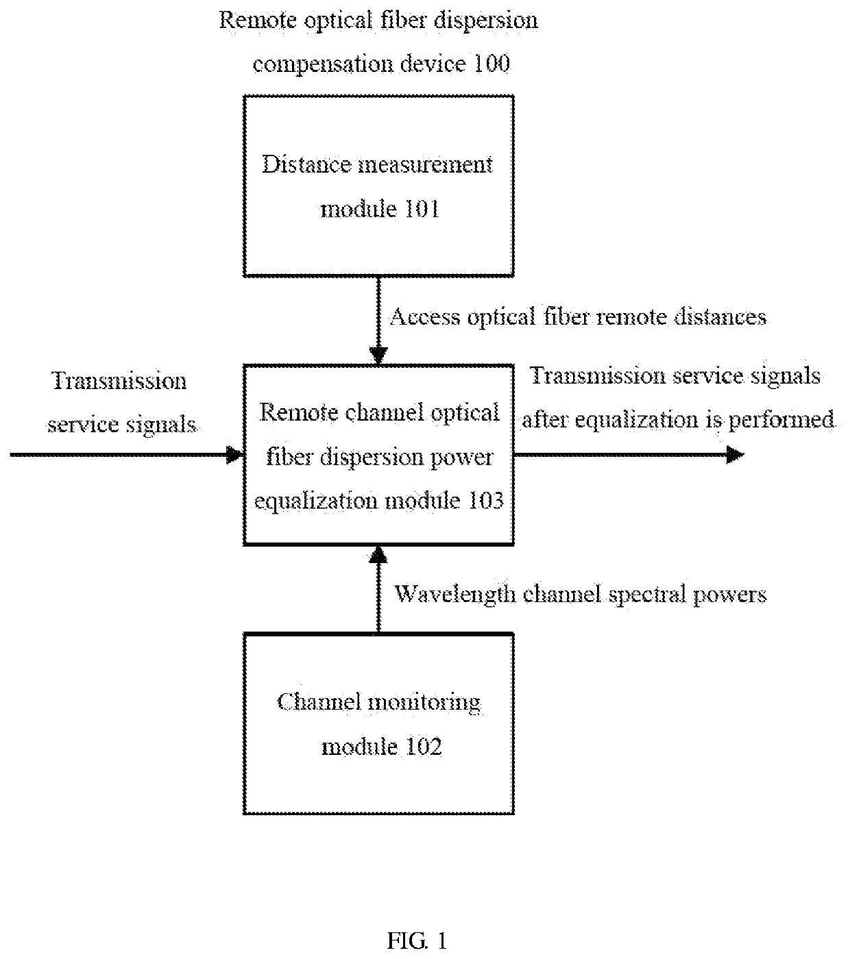
[0028]FIG. 1 shows a schematic structural diagram of a remote optical fiber dispersion compensation device 100 according to an embodiment of the present disclosure.

[0029]As shown in FIG. 1, a remote optical fiber dispersion compensation device 100 provided by the embodiments of the present disclosure comprises: a distance measurement module 1...


PUM


Abstract

Provided by the embodiments of the present invention are a remote optical fiber dispersion compensation device and method, the dispersion compensation device comprising: a distance measurement module, used for measuring a remote distance to a remote access optical fiber; a channel monitoring module, used for monitoring the spectral power of a transmission service wavelength channel; and a remote optical fiber dispersion power equalization module, used for compensating the dispersion of a transmission service signal and adjusting the insertion loss of the wavelength channel according to the measured remote distance of the remote access optical fiber and the monitored spectral power of the transmission service wavelength channel. By employing the embodiments of the present invention, compensation amounts of different channels may be flexibly selected by means of a wavelength selection switch, dispersion may be compensated for remote optical fiber transmission and the insertion loss may be adjusted for different channels by presetting dispersion compensation optical fibers of different lengths, thus achieving compensation and equalization of dispersion and power difference introduced by remote optical fibers of different lengths.

Description

TECHNICAL FIELD[0001]The embodiments of the present disclosure relate to the technical field of optical fiber communication, and in particular to a method and a device of remote optical fiber dispersion compensation.BACKGROUND[0002]In an optical fiber access network, different access wavelength channels may be generated at different physical locations and there are different remote distances from a convergence device. Some optical channels may be generated locally at the device, and the remote distance is 0; and some optical channels may be generated outside of 10 kilometers, connected to the local device through the optical fiber, and multiplexed with local services at the optical wavelength level and transmitted to a data center of an upper level.[0003]At present, an optical signal modulated by the PAM4 format is widely used in the optical fiber access network, and has the advantage of bearing higher service capacity with low baud rate. However, this modulation format requires har...

Claims


Application Information

Patent Timeline
IPC IPC(8): H04B10/2525
CPCH04B10/25253H04B10/2525
Inventor XIAO, LIZHANG, WEIQINGBU, QINLIANFU, CHENGPENGCHEN, ZHIQIAO, LIJIE
Owner ACCELINK TECHNOLOGIES CO LTD
Features
  • R&D
  • Intellectual Property
  • Life Sciences
  • Materials
  • Tech Scout
  • Unparalleled Data Quality
  • Higher Quality Content
  • 60% Fewer Hallucinations
Learn More