Power tool
a power tool and power technology, applied in the field of power tools, can solve the problems of 1 complicating assembly, and achieve the effect of simplifying assembly
- Summary
- Abstract
- Description
- Claims
- Application Information
AI Technical Summary
Benefits of technology
Problems solved by technology
Method used
Image

Examples
first embodiment
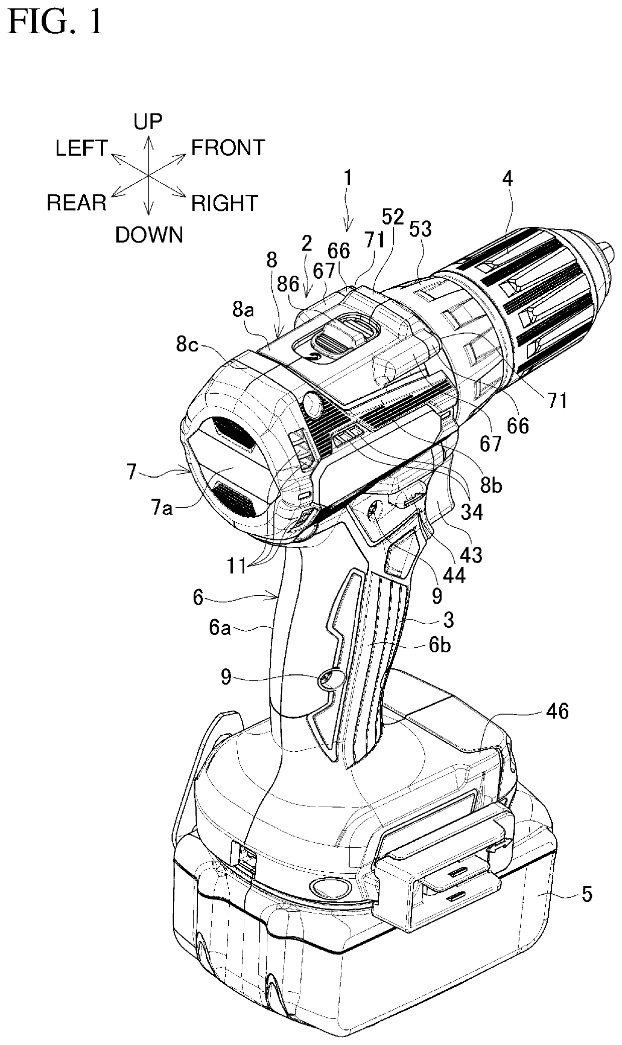
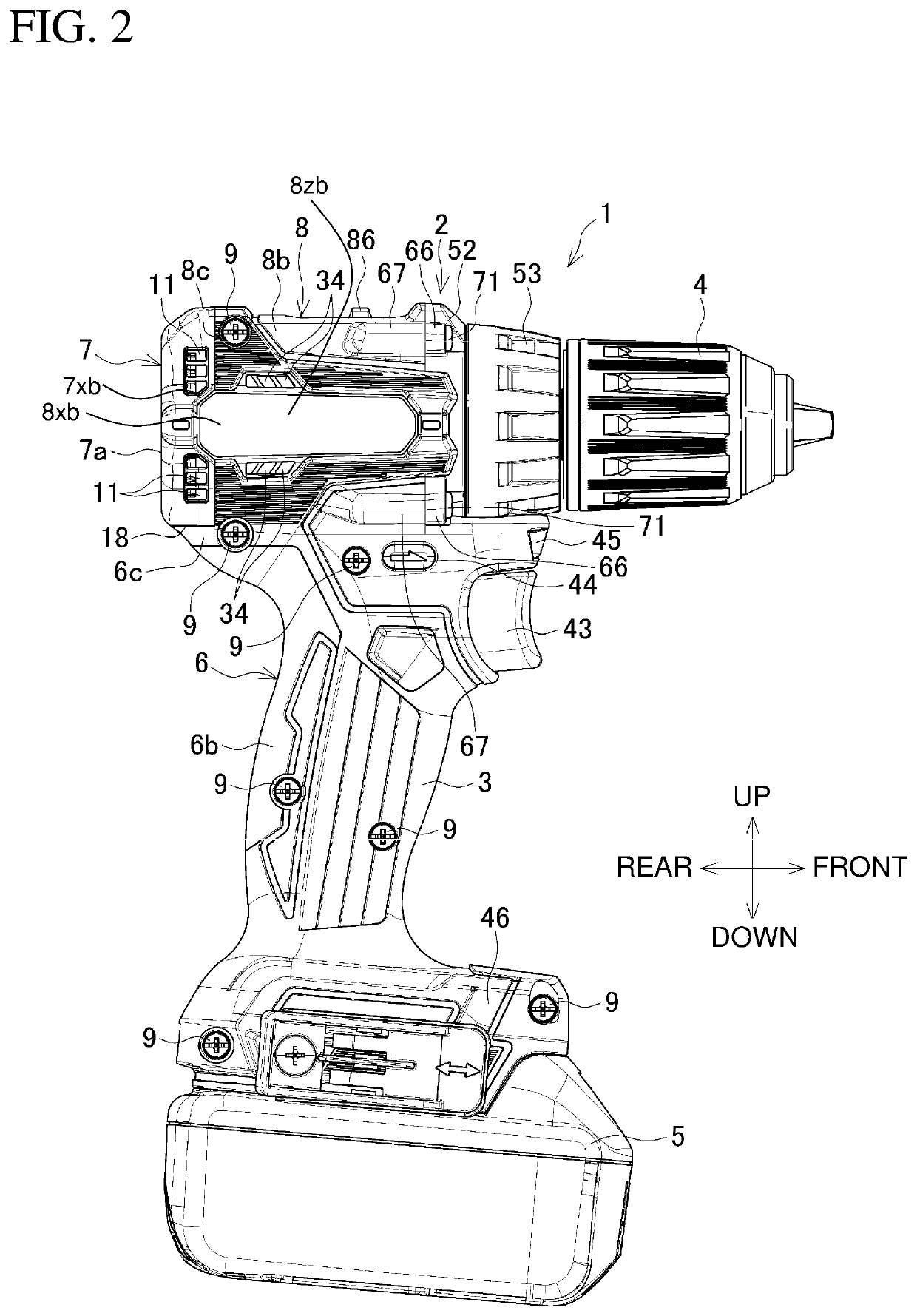
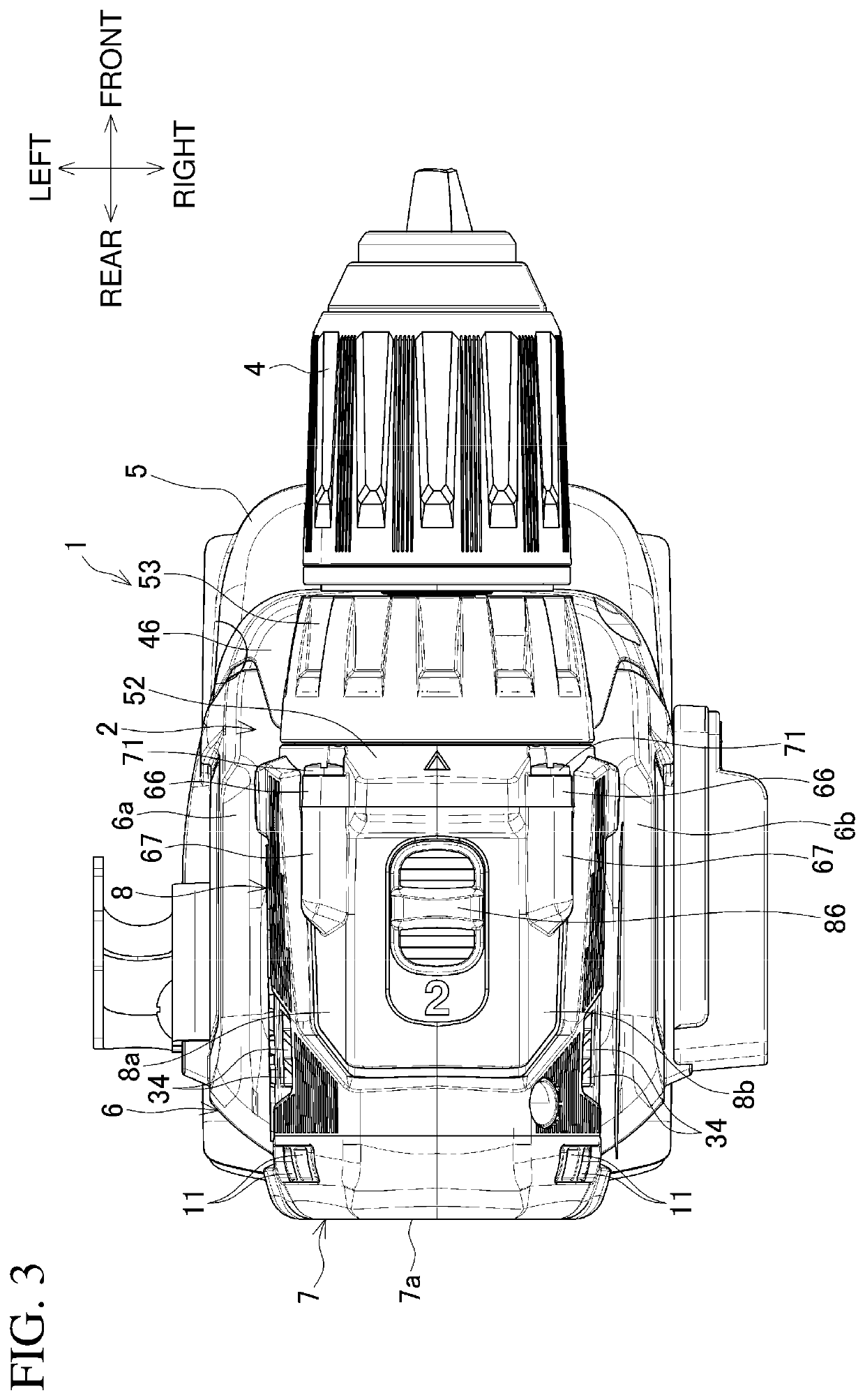
[0039]FIG. 1 is a perspective view of a driver drill as an example of a power tool viewed from the rear. FIG. 2 is a side view of the driver drill. FIG. 3 is a plan view of the driver drill. FIG. 4 is a partially enlarged front view of the driver drill. FIG. 5 is a partially enlarged rear view of the driver drill.
[0040]A driver drill is one example of a power tool. The driver drill 1 includes a body 2 and a grip 3. The body 2 extends in the front-rear direction. The grip 3 protrudes from a lower portion of the body 2. The body 2 and the grip 3 form a T shape as viewed laterally (from left side or right side). The body 2 includes a drill chuck 4 on its front end. The drill chuck 4 can receive a driver bit on its distal end.
[0041]The grip 3 receives a battery pack 5 as a power supply on its lower end. The driver drill 1 includes a housing including a body housing 6 and a rear cover 7. The body housing 6 includes a cylindrical motor housing 8 and the grip 3 that are connected to each o...
second embodiment
[0088]Other embodiments of the present invention will now be described. A second embodiment is the same as the first embodiment except the shape and the holding structure of the rear cover. The same components as in the above embodiment are given the same reference numerals and will not be described repeatedly.
[0089]In a driver drill 1A shown in FIGS. 11 to 14, the body housing 6 does not have an engagement tab in contact with the lower surface of a rear cover 7A unlike in the first embodiment. The motor housing 8 thus has the totally flat rear end surface 8c along the entire circumference. The rear cover 7A has a lower portion, rather than the flat surface, integral with a hanging part 7c replacing the engagement tab.
[0090]The driver drill 1A also eliminates screwing portions, such as screw bosses for fastening the rear cover 7A, in the motor housing 8. The use of the rear cover 7A thus reduces the entire length and downsizes the motor housing 8 in the radial direction. The use of ...
third embodiment
[0091]In a driver drill 1B described in FIGS. 15 to 18, the rear portion of the motor housing 8 extends to a position at which the rear end surface 8c is located behind the fan 33. The left and right housings 8a and 8b have semicircular, circumferential receiving grooves 105 on their inner surfaces behind the fan 33.
[0092]The rear cover 7B is a circular plate as viewed from the front rather than a cap. The rear cover 7B has the bearing holder 10 at the center of its front surface. The rear cover 7B fitted with the receiving grooves 105 is held by the left and right housings 8a and 8b. The rear cover 7B is thus located frontward from the rear end surface 8c of the motor housing 8 and is unexposed as viewed laterally. The motor housing 8 has the outlets 11 in its right and left side surfaces and outward from the fan 33.
[0093]The driver drill 1B also eliminates screwing portions, such as screw bosses for fastening the rear cover 7B, in the motor housing 8. The use of the rear cover 7B ...
PUM
 Abstract
Description
Claims
Application Information
 - R&D Engineer
- R&D Manager
- IP Professional
- Industry Leading Data Capabilities
- Powerful AI technology
- Patent DNA Extraction
Browse by: Latest US Patents, China's latest patents, Technical Efficacy Thesaurus, Application Domain, Technology Topic.
© 2024 PatSnap. All rights reserved.Legal|Privacy policy|Modern Slavery Act Transparency Statement|Sitemap