Eureka AIR delivers breakthrough ideas for toughest innovation challenges, trusted by R&D personnel around the world.

Support structures and interfaces

Active Publication Date: 2021-10-28
HEWLETT PACKARD DEV CO LP
View PDF0 Cites 1 Cited by
  • Summary
  • Abstract
  • Description
  • Claims
  • Application Information

AI Technical Summary

Benefits of technology

This patent describes a support structure generator for 3D printing. The generator creates a 3D model and a support structure to help the 3D model print without collapsing or getting stuck during the printing process. The technology outlined in the patent makes it easier to create complex models with detailed support structures. The method of operation allows for the efficient and accurate formation of support structures. The patent also includes illustrations of the support structure generator in use, and a cross-sectional view of the 3D model and the support structure. Overall, the support structure generator improves the efficiency and accuracy of 3D printing.

Problems solved by technology

During the sintering phase, portions of the object may be subject to sagging or other deformation.

Method used


Image

  • Support structures and interfaces
  • Support structures and interfaces
  • Support structures and interfaces

Examples


Embodiment Construction

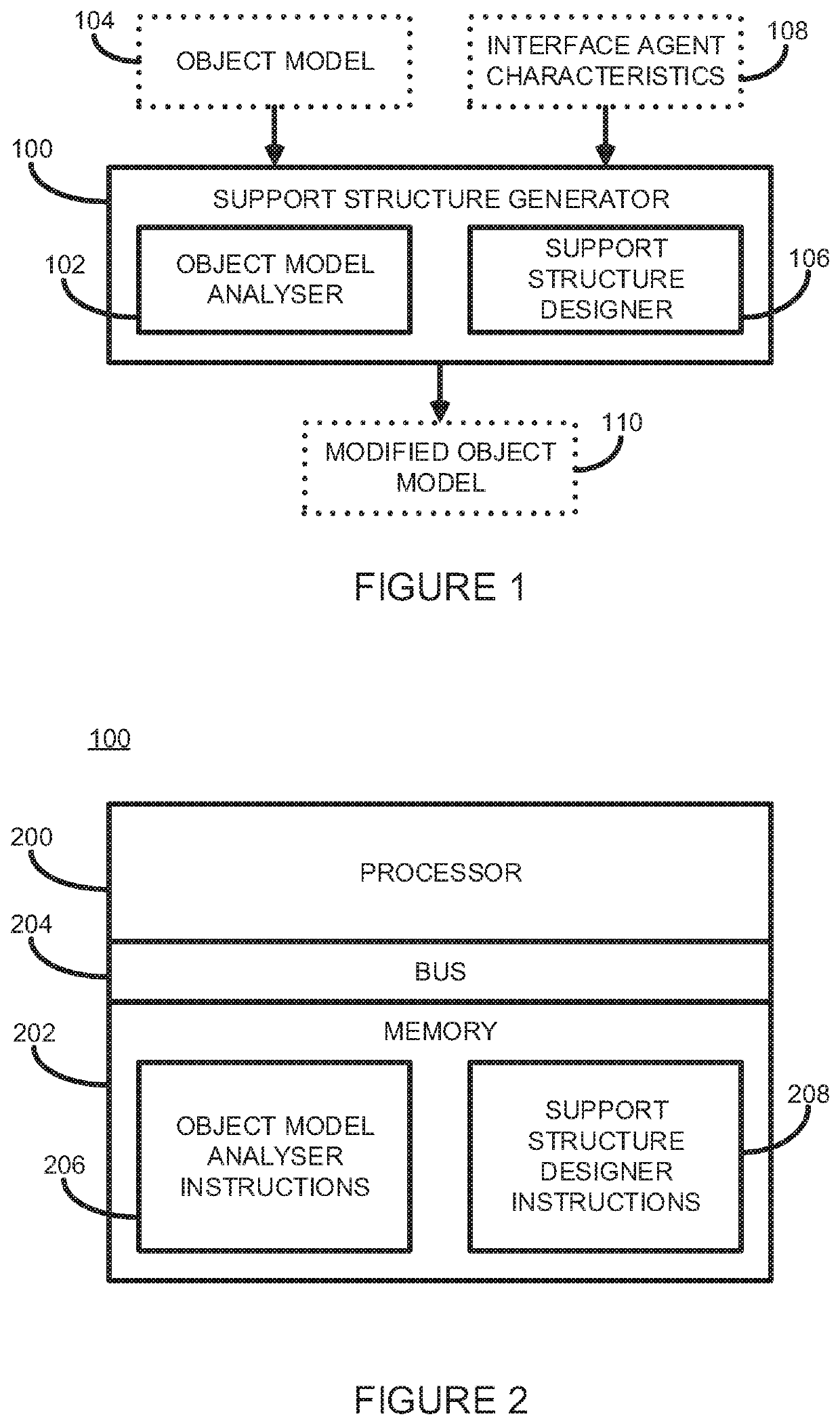
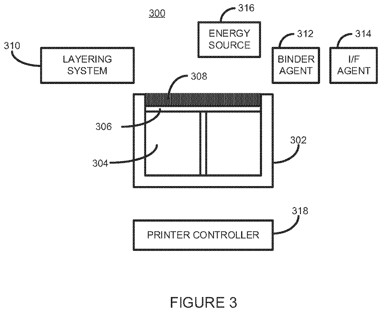
[0016]To add support structures to a green part, a software application may be used to analyse the object model of an object to be generated and, based on the geometry of object to be generated and an intended orientation of the object during the sintering phase, may calculate the position, geometry, and number of support structures to be added to the object model. Such software applications may employ, for example, a physics-based model analysis.

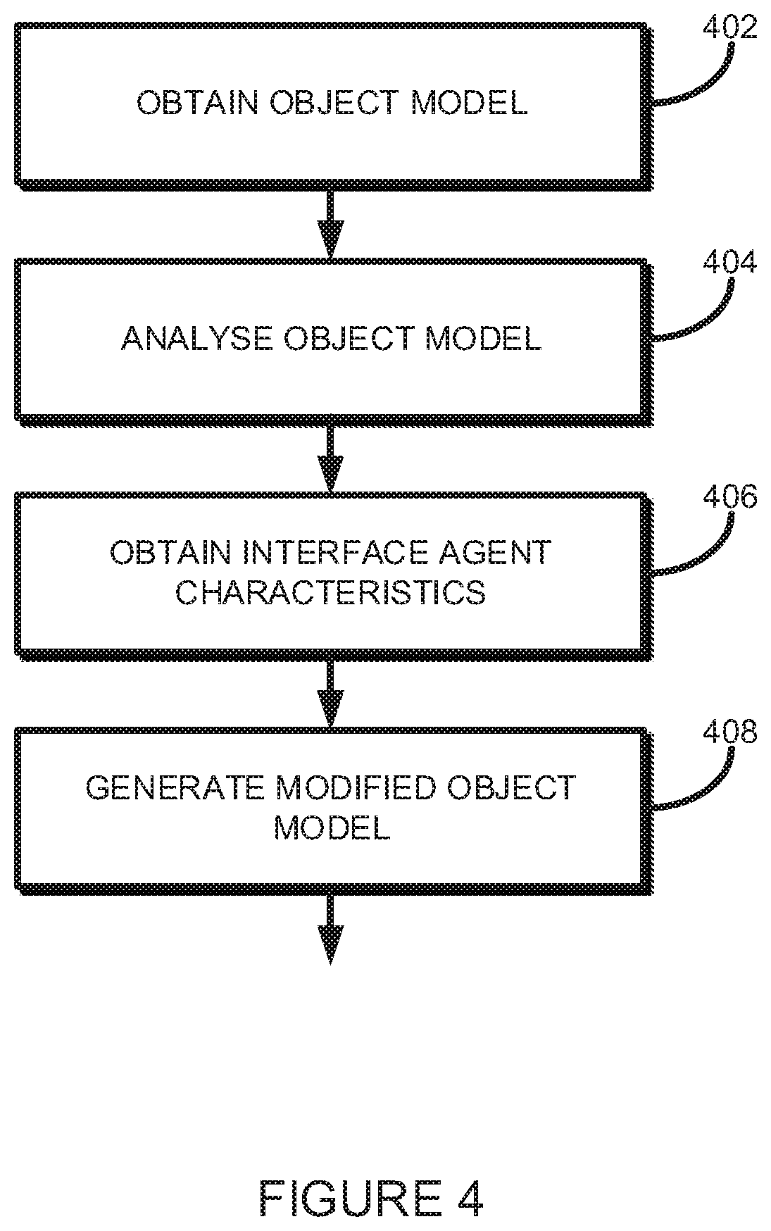
[0017]The modified object model, defining both the object to be formed and any support structures, is used by a 3D printer to generate, on a layer-by-layer basis, a green part comprising the object and the support structures. For example, a 3D printer may be controlled, based on slices of the modified object model, to apply a binder agent on portions of each layer of formed build material corresponding to layers of the object and / or support structures to be generated. Since each layer is formed of the same build material, both the object an...


PUM

PropertyMeasurementUnit
Fractionaaaaaaaaaa
Fractionaaaaaaaaaa
Fractionaaaaaaaaaa

Abstract

According to one example there is provided a non-transitory computer readable storage medium comprising instructions that, when executed by a processor, cause the processor to: obtain an object model; analyse the object model; obtain characteristics of an interface agent; generate a modified object model comprising a support structure and an interface between the support structure and the object, the interface being such that after generation of a 3D printed green part and after sintering thereof, the support structure may be released with a predetermined force; and controlling a 3D printer to generate a 3D printed green part based on the modified object model.

Description

BACKGROUND[0001]3D printing, or additive manufacturing, techniques can be used to produce objects having complex geometries in a wide-range of materials including thermoplastics, polymers, ceramics, and metal.[0002]Powder-bed 3D printing techniques form a layer of a typically particulate or powder-based build material, and then selectively solidify portions of each formed layer to build up layers of a 3D object being generated.[0003]Metal objects may be generated, for example, by applying a liquid binder agent to portions of a formed layer of metal particulate build material to bind together those portions of build material corresponding to a layer of a 3D object being generated. The binder agent may be cured, for example using heat and / or ultra violet energy. Such techniques are commonly known as binder jetting.[0004]The completed bound object, known commonly as a ‘green part’, may then be placed into a sintering furnace where the green part is heated to cause the metal build mater...

Claims


Application Information

Patent Timeline
IPC IPC(8): B29C64/153B29C64/165B29C64/393B22F10/10B22F10/40B33Y10/00B33Y50/02
CPCB29C64/153B29C64/165B29C64/393B33Y50/02B22F10/40B33Y10/00B22F10/10B22F2998/10Y02P10/25B22F10/14B22F10/47B22F10/80B22F3/10
Inventor VAN BROCKLIN, ANDREW L.SHIELDS, JAMES P.
Owner HEWLETT PACKARD DEV CO LP
Why Eureka
Eureka Blog
Learn More