Morphing wing

a wing and wing body technology, applied in the field of morphing wings, can solve the problems of generating steering force and high lift force, affecting the performance of aircraft, and cannot be satisfied, so as to reduce the overall weight, improve aerodynamic efficiency, and simplify the drive unit

Active Publication Date: 2021-10-28
IND UNIV COOP FOUND KOAEA AEROSPACE UNIV
View PDF0 Cites 3 Cited by
  • Summary
  • Abstract
  • Description
  • Claims
  • Application Information

AI Technical Summary

Benefits of technology

[0036]According to the morphing wing of the present invention, maneuvering morphing can be established by only one rotational drive, thereby simplifying the drive unit and reducing the overall weight.
[0037]In addition, because the shape of the continuous airfoil can be maintained even after the maneuvering morphing of the wing, the drag that is generated from the discontinuous surface does not occur, whereby the aerodynamic efficiency can be improved.
[0038]In addition, as the length of the entire chord of the airfoil as well as the angle of the trailing edge portion 200 is increased, the wing surface is increased, whereby the lift force can be greatly increased.

Problems solved by technology

However, these two conditions cannot be satisfied at the same time, and the optimum shape is determined through appropriate compromise.
In particular, a trailing edge portion of the wing is exposed to outside in both of a cruising condition as well as a low-speed condition in which the high lift device is folded, thereby greatly affecting the performance of the aircraft.
In addition, the above-mentioned device changes the aerodynamic force on the flap, which is mechanically separated from the wing, thereby generating the steering force and high lift force.
Thus, since the trailing edge portion A of the wing is separated, a step is generated at a connecting portion, thereby causing a discontinuous surface.
Accordingly, drag is generated at the discontinuous surface, whereby a problem that the aerodynamic efficiency degrades occurs.
In addition, the number of required parts increases due to separation of the trailing edge portion from the wing structure, thereby increasing weight of the aircraft.
At the same time, a magnitude of drag, which is a main cause of loss of propulsion of the aircraft during operation, becomes large.
As a result, above-described features act as a major cause of fuel loss during operation of the aircraft and may also cause an increase in repair costs.

Method used


Image

  • Morphing wing
  • Morphing wing
  • Morphing wing

Examples


Embodiment Construction

[0050]Hereinafter, exemplary embodiments of a morphing wing of the present invention will be described with reference to FIGS. 2 to 10.

[0051]In addition, terms to be described later are terms defined in consideration of functions in the present invention, which may vary according to intentions or practices of users or operators. In addition, the following embodiments do not limit the scope of the present invention and are merely illustrative of the components set forth in the claims.

[0052]In order to clearly describe the present invention, parts irrelevant to the description are omitted, and like reference numerals designate like elements throughout the specification. Throughout the specification, when a part is said to “include” a certain component, it means that it may further include other components, without excluding the other components unless explicitly stated otherwise.

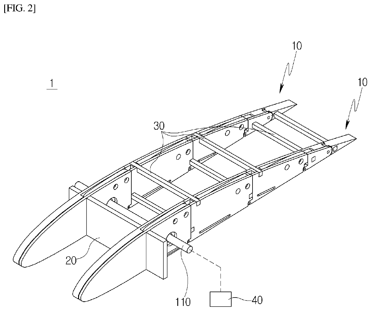
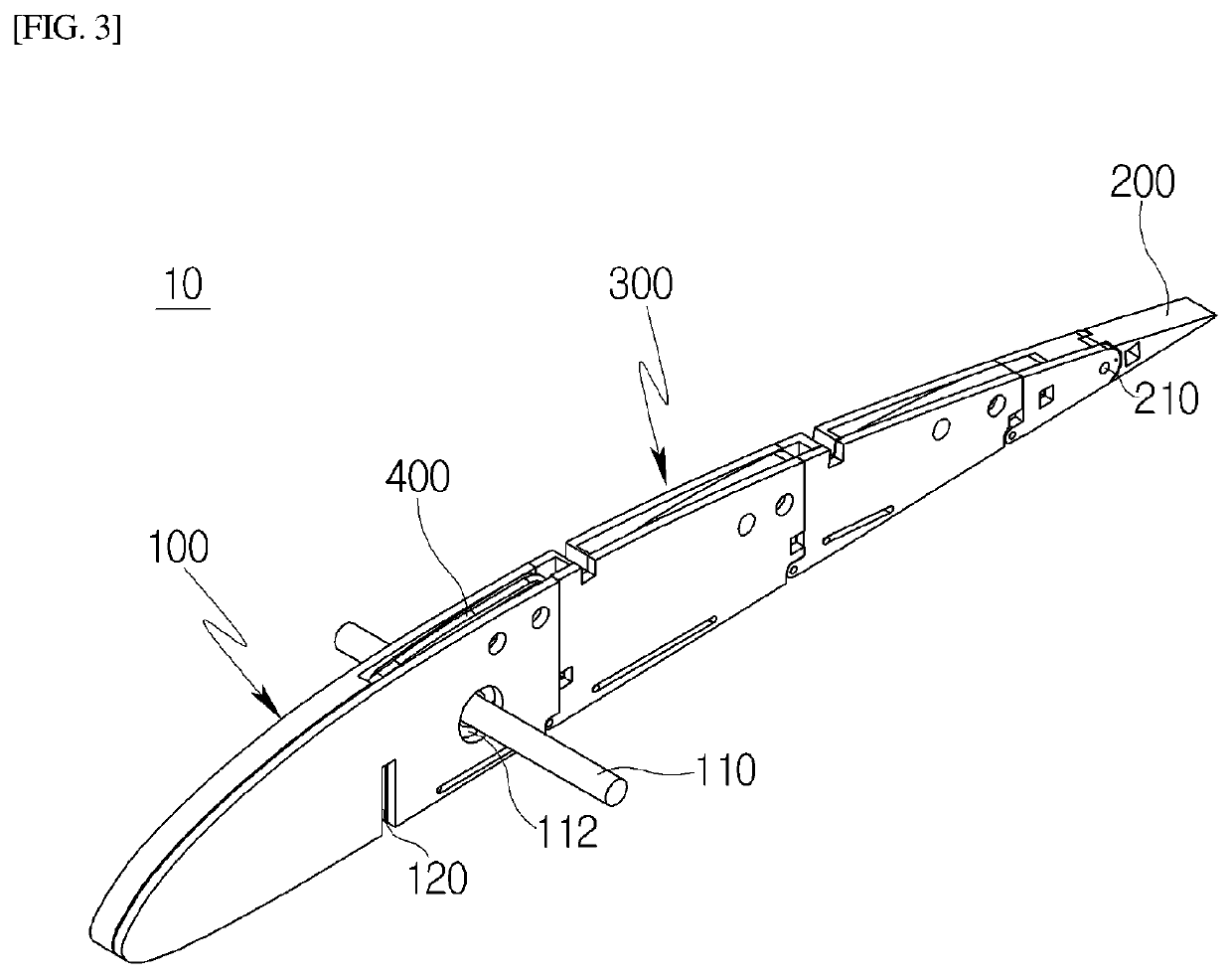
[0053]FIG. 2 is a perspective view illustrating a wing according to an embodiment of the present invention,...


PUM


Abstract

Disclosed is a wing in which, while a continuous surface is maintained, a chord length and camber of an airfoil may be modified via only a rotational drive alone, whereby a structure is simple and aerodynamic efficiency may be improved.

Description

TECHNICAL FIELD[0001]The present invention relates to a morphing wing and, more particularly, to a wing in which, while a continuous surface is maintained, a chord length and camber of an airfoil may be modified via only a rotational drive alone, whereby the structure of the wing is simple and aerodynamic efficiency thereof is improved.BACKGROUND ART[0002]In general, a fixed wing aircraft is provided with a high lift device to generate a steering force to change a flight attitude and flight direction during flight and to increase the lift force during take-off and landing.[0003]Here, the high lift device refers to a device that increases the lift force of an aircraft and enables the lift force replenishment or low-speed flight during takeoff and landing of a high-speed aircraft.[0004]A cross-sectional shape of an aircraft wing directly affects performance of the aircraft and should be designed for optimum performance in aircraft design. In other words, there are two types of wing cr...

Claims


Application Information

Patent Timeline
Patent Type & Authority Applications(United States)
IPC IPC(8): B64C3/48B64C3/18B64C3/26
CPCB64C3/48B64C3/187B64C3/26B64C3/182B64C3/185B64C3/14B64C2003/142
Inventor BAE, JAE SUNGLEE, HYUN CHULLEE, SOO YONG
Owner IND UNIV COOP FOUND KOAEA AEROSPACE UNIV
Why Eureka
Try Eureka