
Apparatus configured to model three-dimensional modeled object, apparatus configured to fly particles, and method of modeling three-dimensional modeled object

Pending Publication Date: 2021-11-04
RICOH KK
View PDF0 Cites 1 Cited by
  • Summary
  • Abstract
  • Description
  • Claims
  • Application Information

AI Technical Summary

Benefits of technology

The patent aims to enhance the quality of modeling.

Problems solved by technology

Unfortunately, the configuration disclosed.

Method used


Image

  • Apparatus configured to model three-dimensional modeled object, apparatus configured to fly particles, and method of modeling three-dimensional modeled object
  • Apparatus configured to model three-dimensional modeled object, apparatus configured to fly particles, and method of modeling three-dimensional modeled object
  • Apparatus configured to model three-dimensional modeled object, apparatus configured to fly particles, and method of modeling three-dimensional modeled object

Examples


example 1-1 to example 1-6

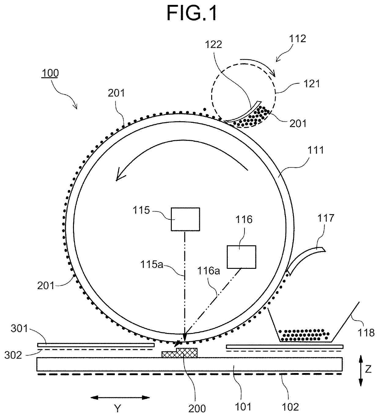
[0163]As illustrated in Table 1, PEEK (Examples 1-1 and 1-2), PA12 (Examples 1-3 and 1-4), and PET (Examples 1-5 and 1-6) were used as the resin (modeling material 201). Then, the surface temperature of the modeled object 200 before heating was set to a temperature lower than the melting point, and the surface temperature when the heated resin reaches the surface (arrival surface temperature) was set to the glass transition temperature Tg or higher (Examples 1-1, 1-3, and 1-5) or the crystallization temperature Tc or higher (Examples 1-2, 1-4, and 1-6). The time interval for flying the resin was “L×L / 200 [ms]” or longer, 0.1 s, in any case.

[0164]The ambient temperature was set to 25° C. in any case. The temperature was measured using the product name FT-H20 manufactured by KEYENCE CORPORATION. The time interval was measured using the product name NR-500 manufactured by KEYENCE CORPORATION.

[0165]The melted state was evaluated for Example 1-1 to Example 1-6, and the evaluation results...

example 2-1

[0179]PES was used as the resin (modeling material 201), and the temperature was set to 250° C. before radiation of laser light and 360° C. after radiation. In this case, the viscosity before radiation was 3.0×10² Pa·s and 6.0×10² Pa·s after radiation.

example 2-2

[0180]PVC was used as the resin (modeling material 201), and the temperature was set to 50° C. before application of energy of laser light and 150° C. after application. In this case, the viscosity before radiation was 4.0×10³ Pa·s and after radiation 5.0×10² Pa·.

[0181]The temperature was measured using the product name FT-H20 manufactured by KEYENCE CORPORATION. The viscosity was measured according to J158803:2011.

[0182]The melted state was evaluated for Examples 2-1 and 2-2, and the evaluation results are illustrated in Table 2. The sign “Good” in the evaluation result indicates that the modeling material is melted, and the modeled object and the modeling material are bonded.

TABLE 2BeforeImmediatelyEvaluationradiationafter radiation(effect)SurfaceSurfaceMeltedResintemperatureviscositytemperatureviscositystateExamplePES250° C.3.0 × 103360° C.6.0 × 102Good2-1[Pa · s][Pa · s]ExamplePVC 50° C.4.0 × 103150° C.5.0 × 102Good2-2[Pa · s][Pa · s]

[0183]According to these examples, for a non-...


PUM

PropertyMeasurementUnit
viscosityaaaaaaaaaa
diameteraaaaaaaaaa
diameteraaaaaaaaaa

Abstract

An apparatus configured to model a three-dimensional modeled object, includes a carrier, an energy applying unit, and a flying unit. The carrier is configured to carry a modeling material. The energy applying unit is configured to apply energy to a surface of a modeled object. The flying unit is configured to fly the modeling material carried on the carrier toward the surface of the modeled object, the energy being applied to the surface.

Description

CROSS-REFERENCE TO RELATED APPLICATIONS[0001]The present application is a continuation application of International Application No. PCT / JP2020 / 010110, filed Mar. 9, 2020, which claims priority to Japanese Patent Application No. 2019-042166, filed Mar. 8, 2019, Japanese Patent Application No. 2019-089260, filed May 9, 2019, Japanese Patent Application No. 2019-139461, filed Jul. 30, 2019, Japanese Patent Application No, 2019-175820, filed Sep. 26, 2019, and Japanese Patent Application. No. 2020-024417, filed Feb. 17, 2020. The contents of these applications are incorporated herein by reference in their entirety.BACKGROUND OF THE INVENTION1. Field of the Invention[0002]The present invention relates to an apparatus configured to model a three-dimensional modeled object, an apparatus configured to fly particles, and a method of modeling a three-dimensional modeled object.2. Description of the Related Art[0003]Apparatuses for modeling a three-dimensional modeled object are generally know...

Claims


Application Information

Patent Timeline
Patent Type & Authority Applications(United States)
IPC IPC(8): B29C64/165B29C64/273B29C64/295B29C64/245B29C64/336B29C64/223B29C64/314B29C64/232B33Y10/00B33Y30/00B33Y40/10
CPCB29C64/165B29C64/273B29C64/295B29C64/245B29C64/336B29K2105/0094B29C64/314B29C64/232B33Y10/00B33Y30/00B33Y40/10B29C64/223B29C64/141B22F2999/00B22F10/25B22F12/50Y02P10/25B22F12/63B29K2995/0041
Inventor FUJITA, TAKASHISUHARA, HIROYUKISAKAI, KOHJIKOBASHIGAWA, SHOHTATAKEUCHI, ATSUSHITAMURA, ASATOMAEDA, ICHIRONISHIO, TAKUEI
Owner RICOH KK
Learn More