Spliced display device

a display device and splice technology, applied in the field can solve the problems of uneven brightness of spliced display devices and uneven panel brightness

Active Publication Date: 2021-11-04
TCL CHINA STAR OPTOELECTRONICS TECH CO LTD
View PDF0 Cites 1 Cited by
  • Summary
  • Abstract
  • Description
  • Claims
  • Application Information

AI Technical Summary

Benefits of technology

[0026]The present application has advantageous effects as follows: the present application uses the driver device to control any adjacent two of the display areas to be scanned in directions facing each other or facing away from each other, so that adjacent two of the display areas of the display panels spliced together can be scanned in directions opposite to each other, and when the adjacent two display panels receive a same grayscale voltage, the display device has a maximum brightness area or a minimum brightness area located between the adjacent two of the display panels, thereby preventing brightness difference from occurring between adjoining areas of the adjacent two display panels, and improving brightness uniformity of the spliced display device.
as follows: the present application uses the driver device to control any adjacent two of the display areas to be scanned in directions facing each other or facing away from each other, so that adjacent two of the display areas of the display panels spliced together can be scanned in directions opposite to each other, and when the adjacent two display panels receive a same grayscale voltage, the display device has a maximum brightness area or a minimum brightness area located between the adjacent two of the display panels, thereby preventing brightness difference from occurring between adjoining areas of the adjacent two display panels, and improving brightness uniformity of the spliced display device.

Problems solved by technology

Since general source lines themselves have certain impedance, and as the impedance is away from signal sending ends, resistance and capacitance of panels themselves give rise to more influence on signal delay, resulting in a technical problem of uneven brightness of the panels.
A technical problem of uneven brightness of display panels occurs because of impedance of data lines, so that brightness of adjacent display panels is different, resulting in uneven brightness of spliced display devices.

Method used


Image

  • Spliced display device
  • Spliced display device
  • Spliced display device

Examples


Embodiment Construction

[0033]In order to make the purpose, technical solutions, and effects of the present application clearer and clearer, the present application will be described in further detail with reference to the accompanying drawings and examples. It should be understood that the specific embodiments described herein are only used to explain the present application, and are not used to limit the present application.

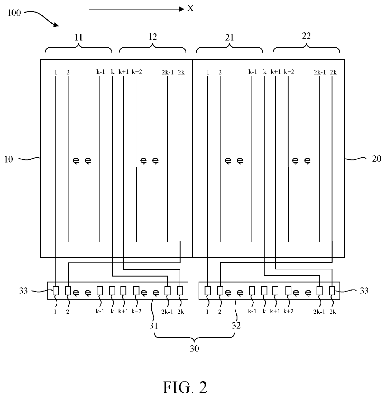
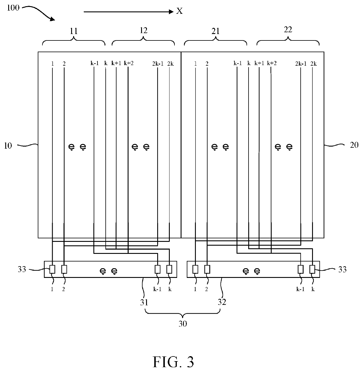
[0034]Current large-sized display panels are generally formed by multiple display panels spliced together. A technical problem of uneven brightness of the panels occurs because of impedance of data lines in each display panel, so that brightness of adjacent display panels is different, resulting in a technical problem of uneven brightness of spliced display devices. The present application provides a spliced display device to overcome the above-mentioned problem. Detailed solutions are described below.

[0035]Please refer to FIGS. 1-6. A spliced display device 100 includes at least two ...


PUM


Abstract

A spliced display device includes at least two display panels and a driver device configured to drive the display panels. Each of the display panels includes at least two display areas disposed side by side in a first direction. Any adjacent two of the display areas are configured to be scanned in directions facing each other or facing away from each other. The display device is provided with a maximum brightness area or a minimum brightness area located between the adjacent two of the display panels.

Description

BACKGROUND OF INVENTION1. Field of Invention[0001]The present invention relates to a technical field of displays, and particularly to, a spliced display device.2. Related Art[0002]With development of large-sized screen televisions, requirements for screen clarity are getting higher and higher, and 8K or higher resolution display panels will certainly become a development trend.[0003]As an increase in size, the panels have longer scan lines and data lines in addition to more pixels. Since general source lines themselves have certain impedance, and as the impedance is away from signal sending ends, resistance and capacitance of panels themselves give rise to more influence on signal delay, resulting in a technical problem of uneven brightness of the panels. For example, grayscale brightness near data signal sending ends of display panels is greater than grayscale brightness away from the data signal sending ends of the display panels. For large-sized display panels, they are generally...

Claims


Application Information

Patent Timeline
Patent Type & Authority Applications(United States)
IPC IPC(8): G09G3/20G06F3/14
CPCG09G3/20G09G2360/04G09G2310/0267G06F3/1438G09G2300/026G09G2320/0233G09G2300/0426
Inventor LIU, JINFENG
Owner TCL CHINA STAR OPTOELECTRONICS TECH CO LTD
Why Eureka
Try Eureka