Control method, transport system, and communication device

a communication device and control method technology, applied in the direction of electrical equipment, process and machine control, instruments, etc., can solve problems such as communication failure, and achieve the effect of reducing or preventing the occurrence of communication failur

Pending Publication Date: 2021-11-11
MURATA MASCH LTD
View PDF0 Cites 0 Cited by
  • Summary
  • Abstract
  • Description
  • Claims
  • Application Information

AI Technical Summary

Benefits of technology

[0005]Accordingly, preferred embodiments of the present invention provide control methods and transport systems each capable of reducing or preventing the occurrence of communication failure in the transport systems.
[0030]According to control methods and transport systems of preferred embodiments of the present invention, it is possible to reduce or prevent the occurrence of communication failure in the transport system.

Problems solved by technology

However, when each of adjacent communication devices continues to transmit the trigger signal constantly, the trigger signals may interfere with each other, causing communication failure.

Method used


Image

  • Control method, transport system, and communication device
  • Control method, transport system, and communication device
  • Control method, transport system, and communication device

Examples


embodiment 1

Preferred Embodiment 1

[0041]A transport system to transport a transportable object will now be described.

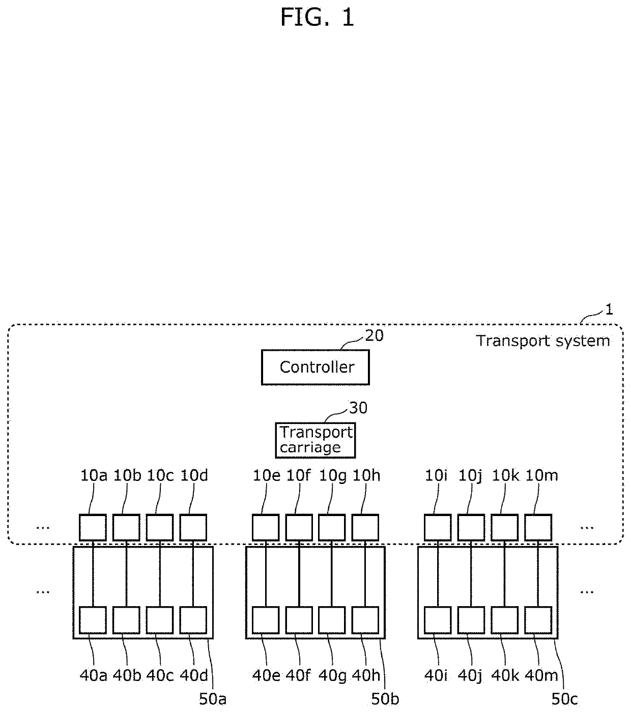
[0042]FIG. 1 is a configuration diagram of transport system 1 according to Preferred Embodiment 1.

[0043]As illustrated in FIG. 1, transport system 1 includes transport carriage 30 to transport a transportable object, a plurality of communication devices 10a to 10k and 10m connected to a plurality of equipment 40a to 40k and 40m to which the transportable object is to be delivered, and controller 20 configured or programmed to control the travel of transport carriage 30.

[0044]As an example, transport system 1 is operated in a semiconductor fab equipped with semiconductor manufacturing apparatuses 50a to 50c as a transport system to transport a FOUP in which a semiconductor wafer is stored as a transportable object.

[0045]Hereinafter, communication devices 10a to 10k and 10m are referred to as communication device 10 unless it is necessary to explicitly distinguish each of them indi...

embodiment 2

Preferred Embodiment 2

[0096]Transport system according to Preferred Embodiment 2, which is partially-modified transport system 1 according to Preferred Embodiment 1, will now be described.

[0097]Transport system 1 according to Preferred Embodiment 1 has been an example configured such that transport carriage transmits a trigger signal. In contrast, a transport system according to Preferred Embodiment 2 is an example configured such that the specific communication device transmits a trigger signal.

[0098]FIG. 5 is a configuration diagram of transport system 1a according to Preferred Embodiment 2.

[0099]As illustrated in FIG. 5, in comparison with transport system 1 according to Preferred Embodiment 1, transport system 1a is configured such that transport carriage according to Preferred Embodiment 1 is replaced by transport carriage 80, communication devices 10a to 10k and 10m according to Preferred Embodiment 1 are replaced by communication devices 60a to 60k and 60m, respectively, and ...


PUM


Abstract

In a control method, a controller obtains equipment specifying information that specifies an equipment to which a transportable object is to be delivered, and a transport carriage obtains carriage position information indicating the position of the transport carriage. Any one of the transport carriage, a specific communication device, and the controller calculates the distance between the transport carriage and the specific communication device based on delivery position information indicating the position of a specific equipment and the carriage position information, and determines whether the distance is not more than a predetermined distance. When the distance is not more than the predetermined distance, one of the transport carriage and the specific communication device transmits, wirelessly to the surroundings, a trigger signal to start wireless communication between the transport carriage and the specific equipment, and performs wireless communication to deliver the transportable object between the transport carriage and the specific equipment.

Description

BACKGROUND OF THE INVENTION1. Field of the Invention[0001]The present invention relates to a control method of a transport system, a transport system, and a communication device.2. Description of the Related Art[0002]Japanese Unexamined Patent Application Publication No. 2015-82574 discloses a transport system including: a plurality of overhead travelling transport carriages each transporting a FOUP (Front Opening Unified Pod) in which a semiconductor wafer is stored; and a plurality of semiconductor manufacturing apparatuses for processing a wafer. Each semiconductor manufacturing apparatus includes a set of a communication device and an access point attached to the apparatus. Each semiconductor manufacturing apparatus is provided with a load port onto which the FOUP is loaded. The communication device is connected to the load port with a parallel cable and also connected to the access point with a LAN (Local Area Network) cable. The access point is wirelessly communicable with eac...

Claims


Application Information

Patent Timeline
Patent Type & Authority Applications(United States)
IPC IPC(8): G05D1/02
CPCG05D1/0276H01L21/67259G05D1/0225H01L21/67733H01L21/67736H01L21/67294G05D1/02H01L21/677G05D1/0221
Inventor OSHIMA, MUNEKUNIITO, YASUHISAKUWAHARA, TETSUYA
Owner MURATA MASCH LTD
Why Eureka
Try Eureka