Multiplexer, high-frequency front-end circuit, and communication device

a high-frequency front-end circuit and multi-channel technology, applied in the direction of dual/triple-band amplifiers, amplifier types, electrical devices, etc., can solve the problem of insufficient improvement of isolation characteristics, and achieve the effect of improving isolation characteristics and isolation characteristics

Active Publication Date: 2021-03-16
MURATA MFG CO LTD
View PDF11 Cites 0 Cited by
  • Summary
  • Abstract
  • Description
  • Claims
  • Application Information

AI Technical Summary

Benefits of technology

[0008]Thus, the minimum distance between the inductor pattern and the ground pattern is not greater than about 1.55 times the minimum pattern width in the ground pattern, such that the minimum distance is able to decrease, and a sufficient capacitance component is therefore able to be obtained by coupling between the inductor pattern and the ground pattern. Thus, an anti-resonance point of the series-arm resonator is able to be adjusted further by LC resonance caused by the capacitance component and an inductance component of the inductor pattern, and an isolation between the first filter and the second filter in a pass band of the second filter is therefore able to be improved further. Furthermore, as the minimum distance decreases, the area of the ground pattern is able to increase, and an isolation between the first filter and the second filter in a pass band of the first filter is therefore able to be improved further. Thus, isolation characteristics between the first filter and the second filter are able to be improved further.
[0014]Thus, for example, when the minimum distance between the inductor pattern and the ground pattern is exceedingly narrow, electrical conduction is likely to occur between the inductor pattern and the ground pattern, whereas, since the minimum distance is not less than about 0.1 times the minimum pattern width, a capacitance component to be obtained is able to be made larger, and the area of the ground pattern is also able to be made larger, while reducing or preventing the occurrence of electrical conduction between the inductor pattern and the ground pattern.
[0016]Thus, the high-frequency front-end circuit enables further improvement in isolation characteristics.
[0019]The multiplexers, the high-frequency front-end circuits, and the communication devices according to preferred embodiments of the present invention enable further improvement in isolation characteristics.

Problems solved by technology

In Japanese Unexamined Patent Application Publication No. 2003-332885, however, the improvement in isolation characteristics is insufficient, and further improvement in isolation characteristics is necessary.

Method used


Image

  • Multiplexer, high-frequency front-end circuit, and communication device
  • Multiplexer, high-frequency front-end circuit, and communication device
  • Multiplexer, high-frequency front-end circuit, and communication device

Examples


embodiment 1

Preferred Embodiment 1

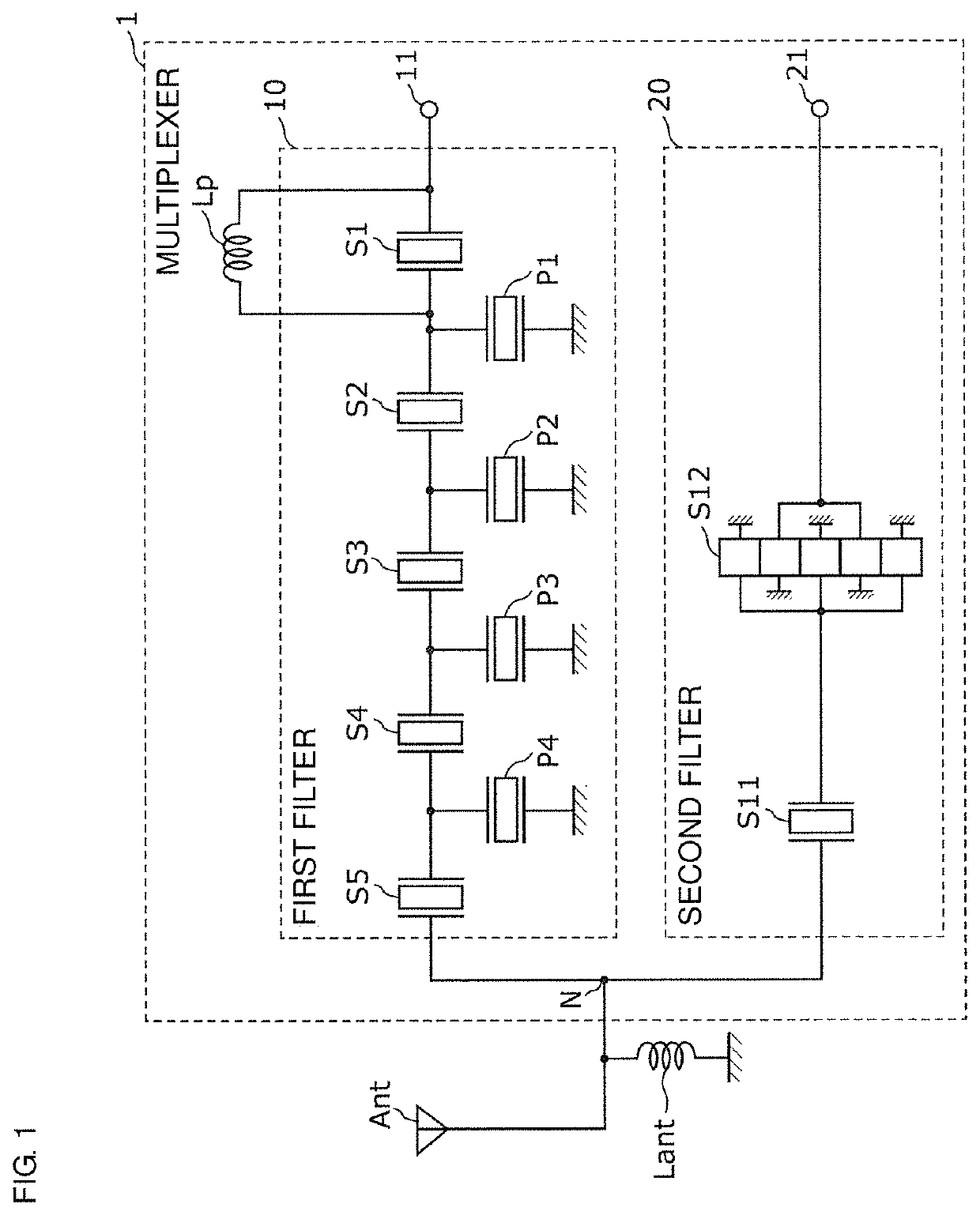
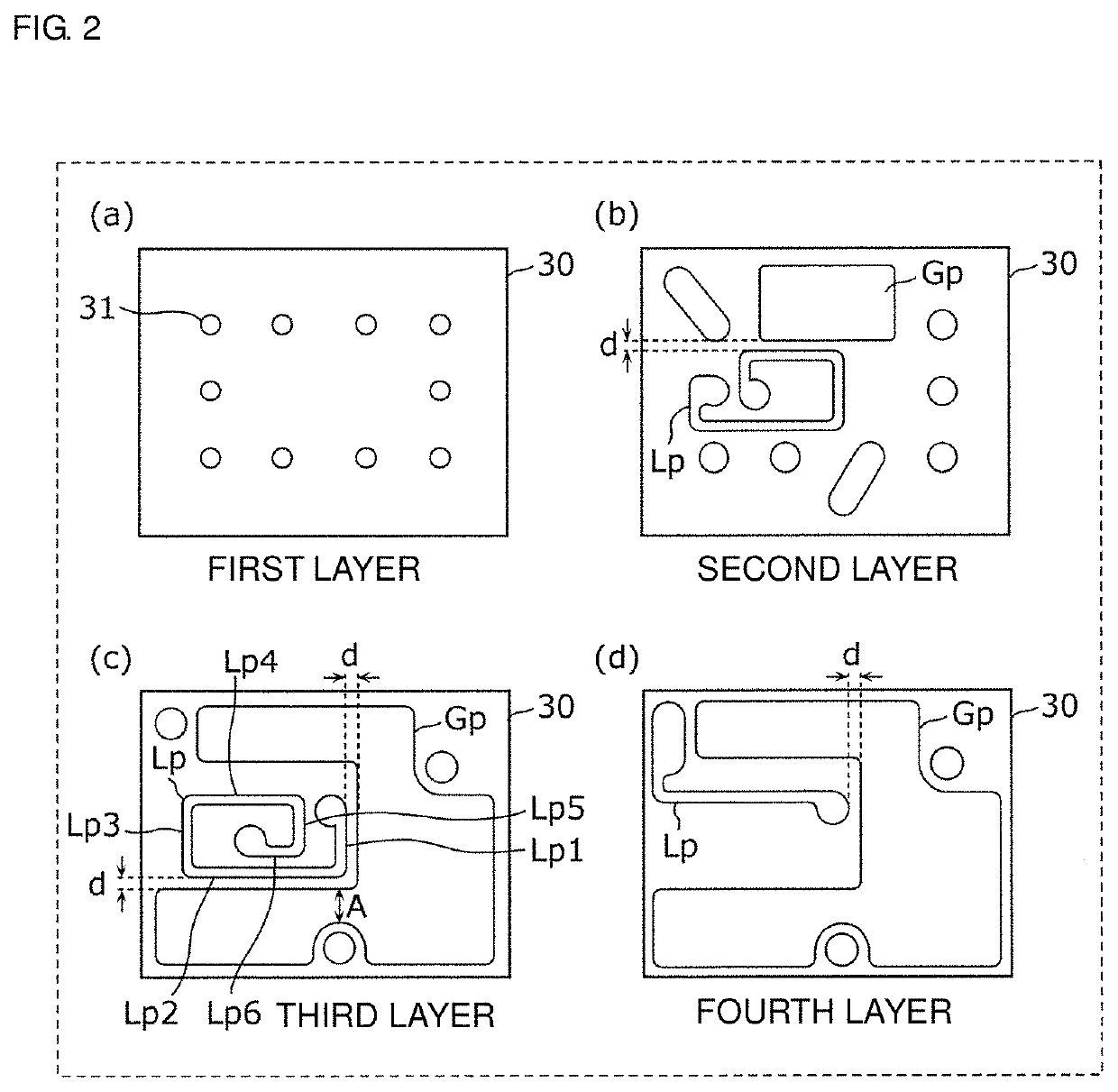
[0028]FIG. 1 illustrates a circuit configuration of a multiplexer 1 according to a Preferred Embodiment 1 of the present invention. As illustrated in FIG. 1, the multiplexer 1 includes a first filter 10, a second filter 20, an inductor Lp, a matching inductor Lant, and input-output terminals 11 and 21. Although not illustrated in FIG. 1, the multiplexer 1 includes a board 30, and the inductor Lp is defined by an inductor pattern provided in the board 30. The board 30 will be described in detail with reference to FIG. 2 described later. Hereinafter, the inductor Lp is also referred to as an inductor pattern Lp. Furthermore, FIG. 1 illustrates a common connection point N of the first filter 10 and the second filter 20. FIG. 1 also illustrates an antenna element ANT, which is not a component of the multiplexer 1. The antenna element ANT is preferably, for example, a multiband-compatible antenna that is compliant with a communication standard, such as LTE (Long Ter...

embodiment 2

Preferred Embodiment 2

[0059]The multiplexer 1 according to the Preferred Embodiment 1 described above may be used in a high-frequency front-end circuit and also in a communication device including the high-frequency front-end circuit. Thus, in the present preferred embodiment, such a high-frequency front-end circuit and such a communication device will be described.

[0060]FIG. 5 illustrates a circuit configuration of a high-frequency front-end circuit 2 and a communication device 3 according to a Preferred Embodiment 2 of the present invention. This figure also illustrates the antenna element ANT connected to the communication device 3. The high-frequency front-end circuit and an RF signal processing circuit (RFIC) 50 define the communication device 3.

[0061]The high-frequency front-end circuit 2 includes the multiplexer 1, and amplifier circuits connected to the multiplexer 1. Here, as amplifier circuits, a power amplifier 40a and a low noise amplifier 40b are illustrated.

[0062]The p...


PUM


Abstract

A multiplexer includes a first filter that is a ladder elastic wave filter including series-arm resonators and parallel-arm resonators, a second filter connected to the first filter at a common connection point, and a board including an inductor pattern defining an inductor connected in parallel with the series-arm resonator, and a ground pattern provided in the layer in which the inductor pattern is provided, so as to be disposed at a distance from and adjacent to the inductor pattern. A minimum distance between the inductor pattern and the ground pattern is not greater than about 1.55 times a minimum pattern width in the ground pattern.

Description

CROSS REFERENCE TO RELATED APPLICATIONS[0001]This application claims the benefit of priority to Japanese Patent Application No. 2017-075233 filed on Apr. 5, 2017 and is a Continuation Application of PCT Application No. PCT / JP2018 / 008527 filed on Mar. 6, 2018. The entire contents of each application are hereby incorporated herein by reference.BACKGROUND OF THE INVENTION1. Field of the Invention[0002]The present invention relates to a multiplexer including a plurality of filters connected with a common connection point, a high-frequency front-end circuit, and a communication device.2. Description of the Related Art[0003]With respect to recent cellular phones, there has been a demand for a single terminal that supports a plurality of frequency bands and a plurality of wireless modes, which are termed multiband compatibility and multimode compatibility. To respond to this demand, directly next to one antenna, a multiplexer is disposed that includes a first filter and a second filter tha...

Claims


Application Information

Patent Timeline
Patent Type & Authority Patents(United States)
IPC IPC(8): H03H9/72H03H9/205H03H9/54H03H9/64H03F3/189
CPCH03H9/725H03F3/189H03H9/205H03H9/54H03H9/6483H04B1/40H03F3/24H03F2200/111H03F2200/451H03H9/0557H03H9/0566H03H9/542H03H9/568H03H9/605H03H9/706H03H9/6489H03H9/72H03H9/145
Inventor KOREEDA, TOSHISHIGE
Owner MURATA MFG CO LTD
Why Eureka
Try Eureka