

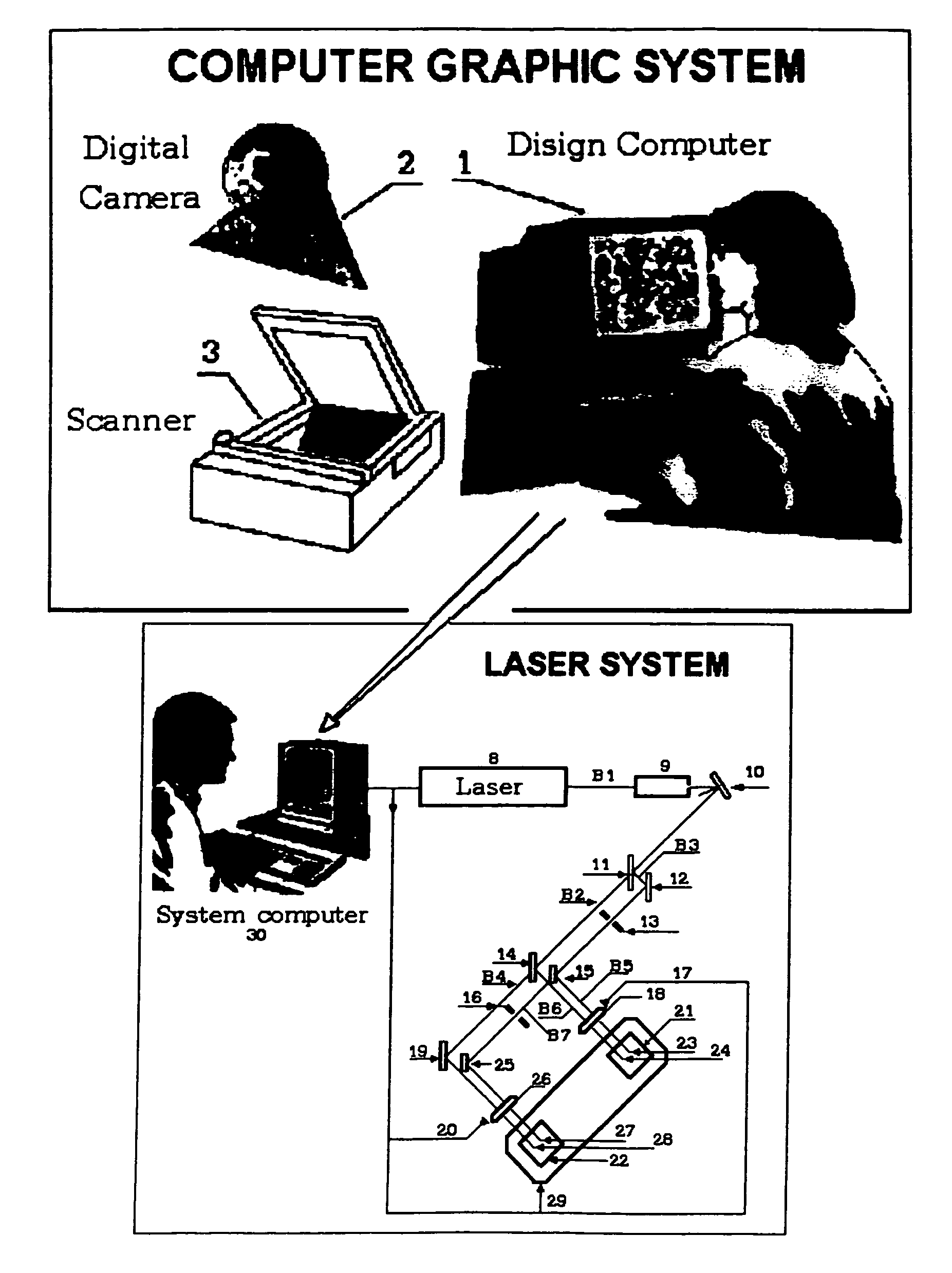
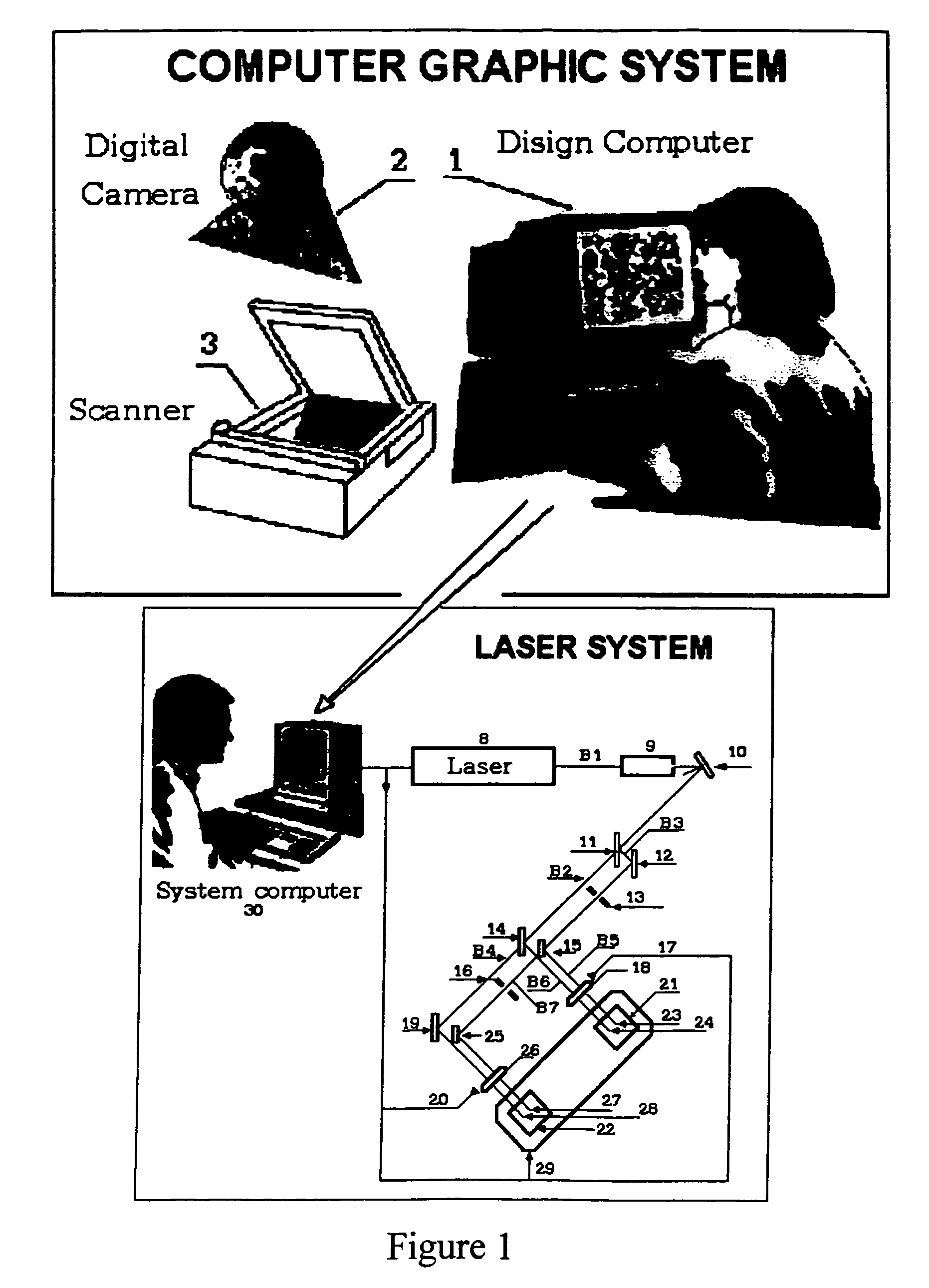
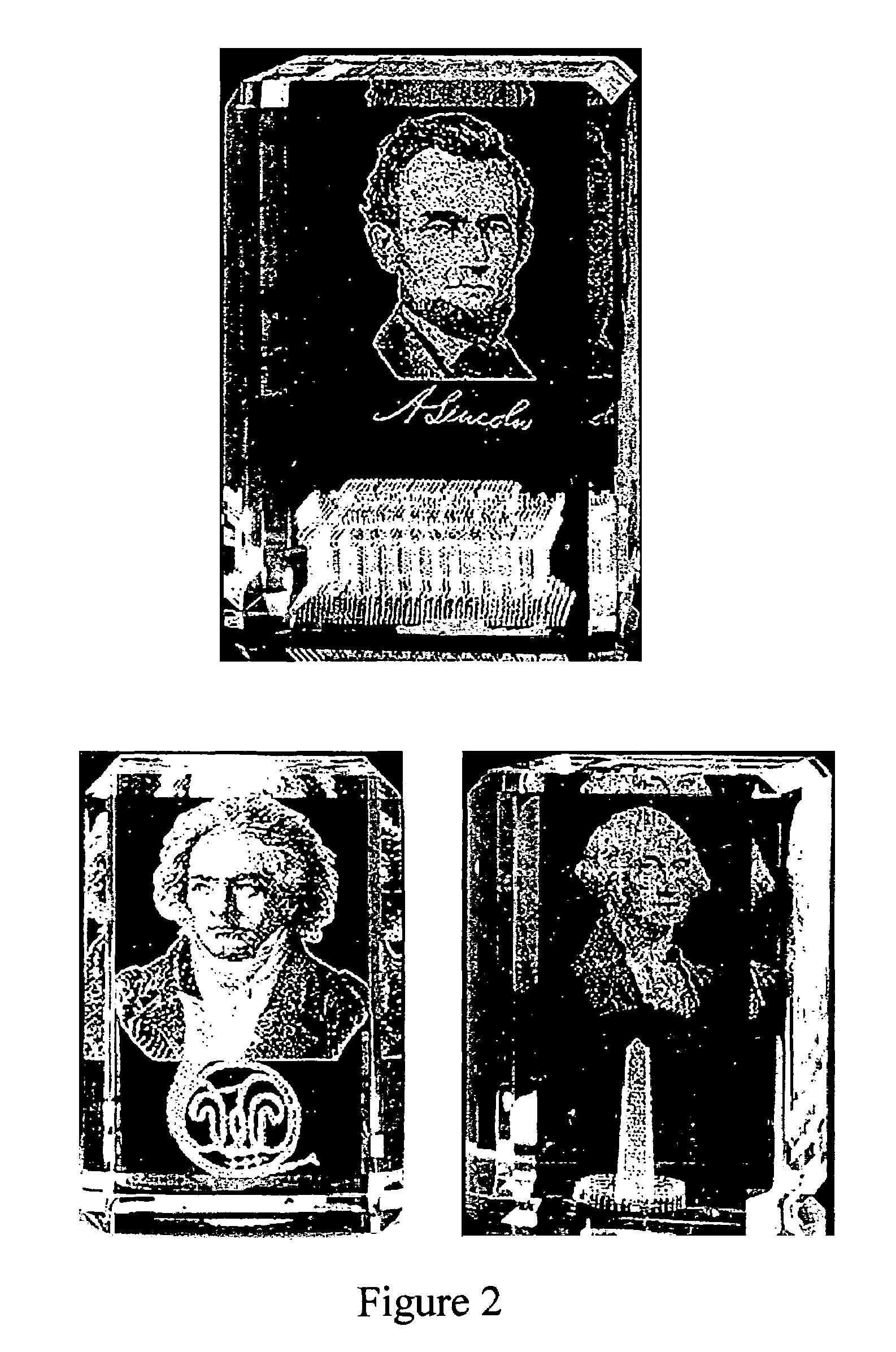
Laser-computer graphics system for generating portrait and 3-D sculpture reproductions inside optically transparent material
a technology of laser-generated etching and 3-d sculpture, which is applied in the direction of material analysis, manufacturing tools, instruments, etc., can solve the problems of low image resolution, unacceptable damage to objects, and the general low resolution of images comprising laser-generated etching points produced by all known systems and methods, so as to improve the contrast of multi-layer portraits and high resolution
- Summary
- Abstract
- Description
- Claims
- Application Information
AI Technical Summary
Benefits of technology
Problems solved by technology
Method used
Image

Examples
first embodiment
[0076]the invention is based upon the physical phenomenon that if a viewer looks at etch points in the material where two or more etch points are aligned one after another and they are not far from each other, then the viewer sees their projection on visual plane (i.e. plane perpendicular to observation direction) as having a brightness greater than a single point. In other words, the greater number of points which are positioned in alignment, the higher the sum of the brightness of their projection. A first method of gray shade generation of the invention has the very important advantage of reducing gray shade fluctuation since the brightness of their projection comprises the average brightness of the separated points.
[0077]By way of illustration, FIG. 5(a) shows an etch point projection having a first brightness. FIG. 5(b) is a projection of two etch points following one after another, this projection having a greater brightness. FIG. 5(c) shows a plurality of different etch point...
second embodiment
[0101]the invention is based upon the physical phenomenon that when the dimensions of an etch point increase, its brightness increases. Different dimensions of etch points can be achieved in at least the following two ways: (1) the dimensions of an etch point increase when the laser radiation energy used to create the point increases; and (2) the dimensions of an etch point increase as the number of laser radiation pulses directed at the same point increases.
[0102]Another embodiment of a method of the present invention consists of the following steps:
[0103]Step B1: This step is the same as step Al of the previous embodiment.
[0104]Step B2: A number of one-shade gray images M are formed from the basic or original image. Unlike the previous method, these images are not identical to the basic image. Instead, a first one-shade image consists only of those areas of the basic image where the gray shade nearest to black is not equal to zero. The second one-shade image consists of only those...
third embodiment
[0121]the invention is based on the physical phenomenon that as the density of points covering an area increases, so does the perceived brightness of the area. The densest coverage corresponds to a white shade and other areas with less than the densest or complete cover comprise other gray shades. The cover arrangement illustrated in FIG. 7(a) can be used to transfer four gray shades: the plurality of #1 points transfers dark gray; the plurality of #1 plus #2 points gives another gray shade; the plurality of #1, #2 and #3 points jointly transfer light gray shade; an the plurality of all #1, #2, #3 and #4 points produces white. By analogy, the cover arrange illustrated in FIG. 7(b) can be used to transfer nine gray shades.
[0122]It should be noted that in accordance with this method some areas are not covered completely and a point structure may be seen by the naked eye. The unpleasant effect of the perceived point structure resulting from the regular position of etch points can be el...
PUM
| Property | Measurement | Unit |
|---|---|---|
| focal length | aaaaa | aaaaa |
| thick | aaaaa | aaaaa |
| length | aaaaa | aaaaa |
Abstract
Description
Claims
Application Information