

Radio-frequency module
- Summary
- Abstract
- Description
- Claims
- Application Information
AI Technical Summary
Benefits of technology
Problems solved by technology
Method used
Image

Examples
first preferred embodiment
[0042]The overall configuration of a radio-frequency module according to a first preferred embodiment of the present invention will first be described below with reference to the drawings.
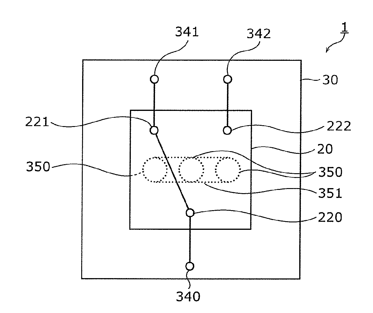
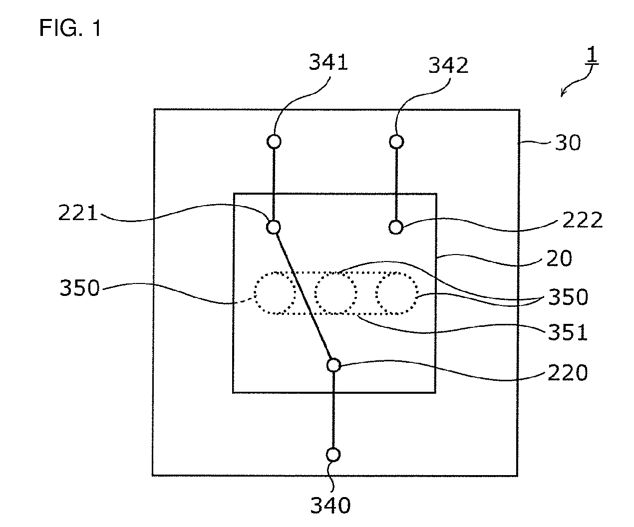
[0043]FIG. 1 is a circuit diagram illustrating the circuit configuration of the radio-frequency module 1.
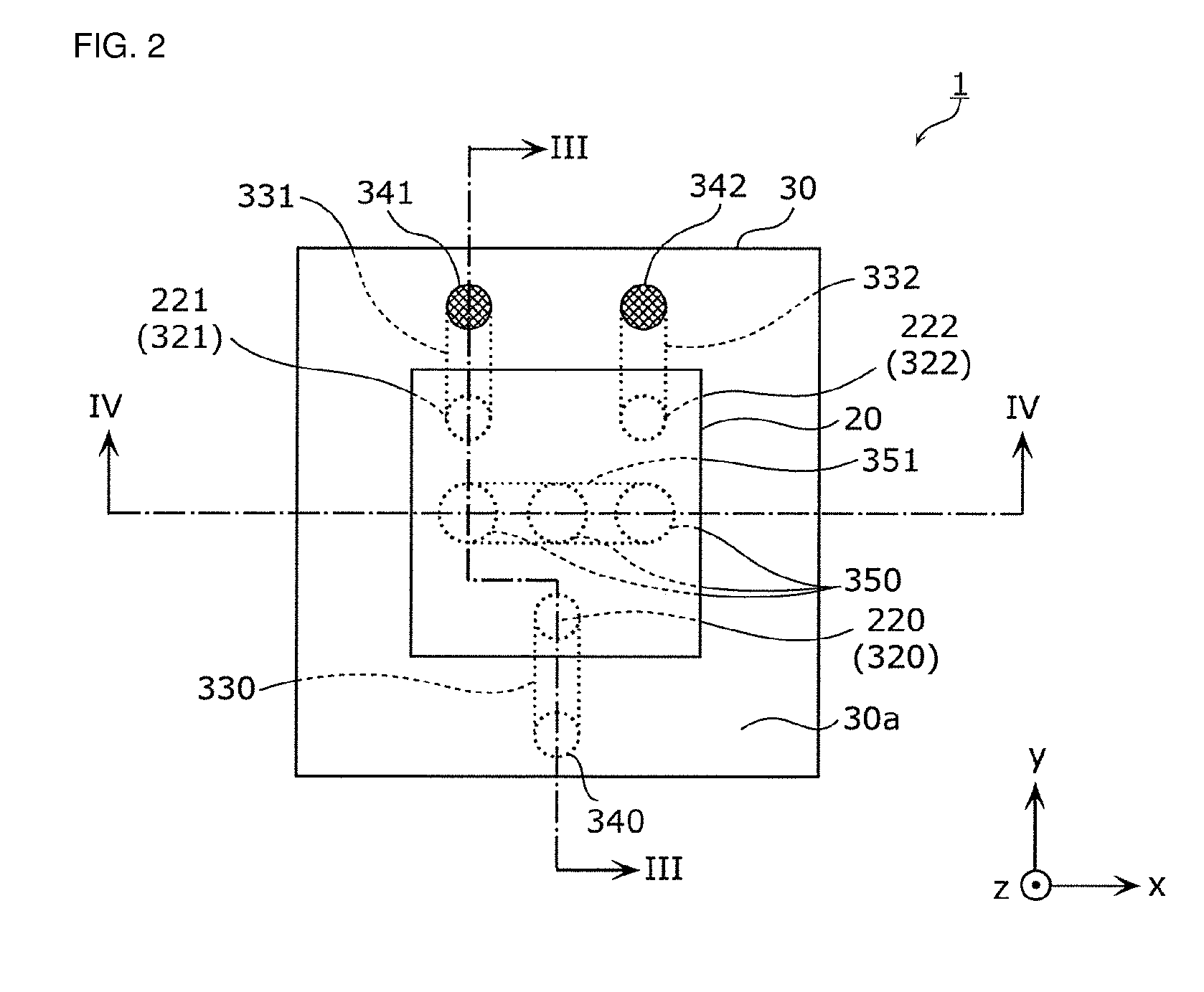
[0044]FIG. 2 is a top view illustrating the external appearance of the radio-frequency module 1.
[0045]FIG. 3 is a sectional view illustrating the structure of the radio-frequency module 1 taken along line III-III of FIG. 2.
[0046]FIG. 4 is a sectional view illustrating the structure of the radio-frequency module 1 taken along line IV-IV of FIG. 2.
[0047]As shown in FIG. 1, the radio-frequency module 1 includes a substrate 30 and a switch IC 20. The switch IC 20 is mounted on the substrate 30 and includes a common terminal 220 and plural selection terminals 221 and 222. The switch IC 20 and the substrate 30 will be discussed below in detail.
[0048]As shown in FIG. 1, the switch IC 20 is a switch cir...
second preferred embodiment
[0086]A radio-frequency module 2 according to a second preferred embodiment of the present invention will now be described below. The radio-frequency module 2 of the second preferred embodiment includes a directional coupler on a substrate. The radio-frequency module 2 will be described below mainly by referring to the points different from the radio-frequency module 1 of the first preferred embodiment.
[0087]The overall configuration of the radio-frequency module 2 will first be discussed below with reference to FIG. 5.
[0088]FIG. 5 is a circuit diagram illustrating the circuit configuration of the radio-frequency module 2.
[0089]As shown in FIG. 5, as in the radio-frequency module 1 of the first preferred embodiment, the radio-frequency module 2 includes a substrate 31 and a switch IC 20. The radio-frequency module 2 also includes a directional coupler 60 and a switch IC 70.
[0090]The configuration of the substrate 31 is similar to that of the substrate 30 of the first preferred embod...
third preferred embodiment
[0112]A radio-frequency module 3 according to a third preferred embodiment of the present invention will be described below. In the third preferred embodiment, the radio-frequency module 3 includes another directional coupler in addition to the elements of the radio-frequency module 2 of the second preferred embodiment, and the number of selection terminals of each of the switch ICs is greater than that of the radio-frequency module 2 of the second preferred embodiment. The configuration of the radio-frequency module 3 and an example of the application modes will be discussed below with reference to FIG. 7.
[0113]FIG. 7 is a circuit diagram illustrating the circuit configuration of the radio-frequency module 3 and an example of the application modes.
[0114]As in the radio-frequency module 2 of the second preferred embodiment, the radio-frequency module 3 includes a substrate 32, switch ICs 21 and 71, and a directional coupler 60, as shown in FIG. 7. In the third preferred embodiment, ...
PUM
 Abstract
Description
Claims
Application Information