Self-rotating spray bar assembly

a self-rotating, spray bar technology, applied in the direction of cleaning process and equipment, cleaning liquids, chemistry apparatus and processes, etc., can solve the problems of damage to the spinner bar contacting debris or bumps in the surface, the speed at which a rotary spinner bar is required to rotate, and the rotation of the spinner bar. achieve the effect of uniform speed control and smooth rotation of the spinner bar

Pending Publication Date: 2021-11-25
WATERBLASTING
View PDF7 Cites 0 Cited by
  • Summary
  • Abstract
  • Description
  • Claims
  • Application Information

AI Technical Summary

Benefits of technology

[0009]The present invention relates generally to a walk-behind device that attaches to an ultra-high pressure pump. The ultra-high pressure pump feeds a hydraulic pump and spinner bar containing nozzles. Pressurized water is connected to the device and used to cause rotation of the hydraulic pump which is coupled to a portable hydraulic tank having a valve to control the rotational speed of the spinner bar. The pressurized water further operates the spinner bar by use of an offset position, wherein rotation is a result of reaction force caused by the pressurized water exiting the nozzles mounted on the spinner bar. The hydraulic pump is fluidly coupled to a small hydraulic reservoir mounted on the handle of the device. The hydraulic reservoir includes a hand operated flow valve to control rotational speed of the spinner. The hydraulic pump and reservoir provide uniform speed control and ensure smooth rotation of the spinner bar.

Problems solved by technology

A problem associated with rotary spinner bars is the need for a motor, such as a pneumatic, electrical or independent hydraulic motor, to cause rotation of the spinner bar.
Another drawback relates to the speed at which a rotary spinner bar is required to rotate to achieve an acceptable surface cleaning.
Most spinner bars rotate at speeds of about 3,000 revolutions per minute, which often results in damage to the spinner bar contacting debris or bumps in the surface.

Method used


Image

  • Self-rotating spray bar assembly

Examples


Embodiment Construction

[0020]While the present invention is susceptible of embodiment in various forms, there is shown in the drawings and will hereinafter be described a presently preferred embodiment with the understanding that the present disclosure is to be considered an exemplification of the invention and is not intended to limit the invention to the specific embodiments illustrated.

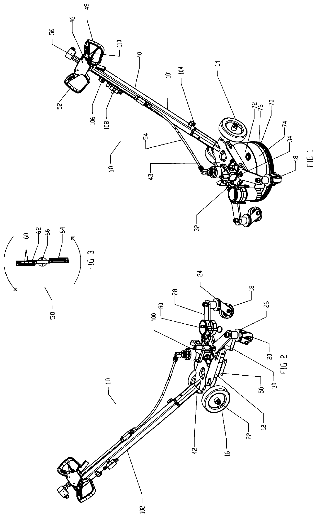
[0021]Now referring to the figures, illustrated is a self-rotating device 10 for cleaning with ultra-high water pressure, preferably 40,000 psi. The self-rotating device 10 is formed from a base 12 supported by a pair of rear wheels 14, 16 and a pair of front wheels 18, 20. The rear wheels 14, 16 can be mounted on a common axle 22, which allows for straight line tracking. The front wheels 18, 20 are preferably mounted on casters 24, 26, which allow ease of steering by taking weight off the rear wheels. The stance of the base 12 can be further adjusted by positioning of pivot arms 28, 30 using wing nut fasteners 32, 34, t...


PUM


Abstract

A self-rotating device for cleaning with ultra-high water pressure having a base supported by front and rear wheels with a handle extending therefrom. A spray bar assembly with a plurality of nozzles constructed and arranged to cause rotation of the spray bar through fluid discharge is mounted beneath the base. A hydraulic pump is positioned with spray bar and coupled to a reservoir mounted on the handle. The hydraulic pump is rotated by the spray bar assembly, causing hydraulic fluid to recirculate through the reservoir, wherein an adjustable flow valve permits control of the spray bar assembly rotation speed.

Description

PRIORITY CLAIM[0001]In accordance with 37 C.F.R. 1.76, a claim of priority is included in an Application Data Sheet filed concurrently herewith. Accordingly, the present invention claims priority to U.S. Provisional Patent Application No. 62 / 984,017, entitled “SELF-ROTATING SPRAY BAR ASSEMBLY”, filed Mar. 2, 2020; the contents of which are incorporated herein by reference.FIELD OF INVENTION[0002]The present invention generally relates to surface cleaning systems, and more particularly, to a self-rotating spray bar assembly, wherein the speed of the spray bar is controlled by water pressure.BACKGROUND INFORMATION[0003]Surface cleaning apparatus, such as pressure washers, are useful for cleaning a variety of objects. Although there are many types of pressure washing systems, a typical system utilizes an engine that powers a high pressure pump. The inlet side of the high pressure pump is connected to a low pressure water source, such as a water tank or a municipal water supply, while t...

Claims


Application Information

Patent Timeline
Patent Type & Authority Applications(United States)
IPC IPC(8): B05B3/06B08B3/02B05B13/00
CPCB05B3/06B08B3/024B08B2203/027B08B2203/0264B05B13/005B08B3/028B08B2203/0229B05B14/30B05B3/003B05B15/63
Inventor CROCKER, JAMES
Owner WATERBLASTING
Why Eureka
Try Eureka