
Artificial wave generation surfing facility

a technology of artificial waves and surfing facilities, applied in the field of water amusement facilities, can solve the problems of extending the assembly and dismantling time, heavyweight and cumbersome, and excluding the horizontally arranged section to which water is pumped

Active Publication Date: 2021-12-02
WAVEBOX LTD
View PDF0 Cites 1 Cited by
  • Summary
  • Abstract
  • Description
  • Claims
  • Application Information

AI Technical Summary

Benefits of technology

The invention has a simpler and lighter design, takes less time to assemble and disassemble, and can control how water flows and stabilizes the flow.

Problems solved by technology

One disadvantage of the prior art is the inclusion of the horizontally arranged section to which water is pumped.
It makes the structure more complex, heavyweight and cumbersome, extending the assembly and dismantling time.
Also, the side walls of the surfing facility will be moved together to stabilize and regulate the water flow, which gives rise to further technical difficulties and the need to use additional drives and actuators.

Method used


Image

  • Artificial wave generation surfing facility
  • Artificial wave generation surfing facility
  • Artificial wave generation surfing facility

Examples


Embodiment Construction

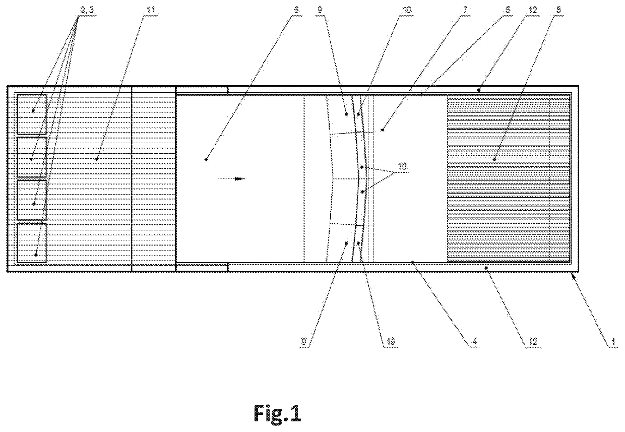
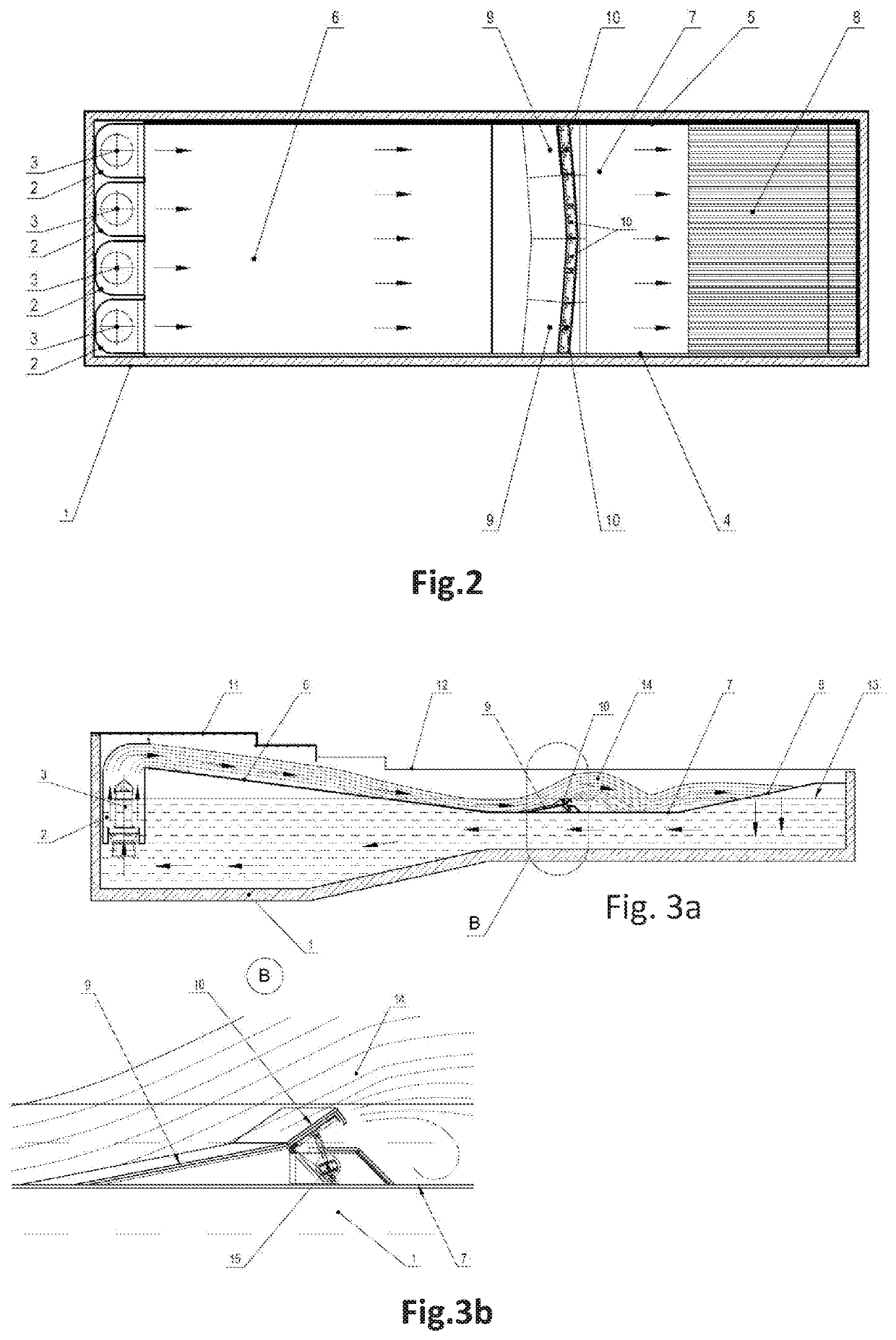
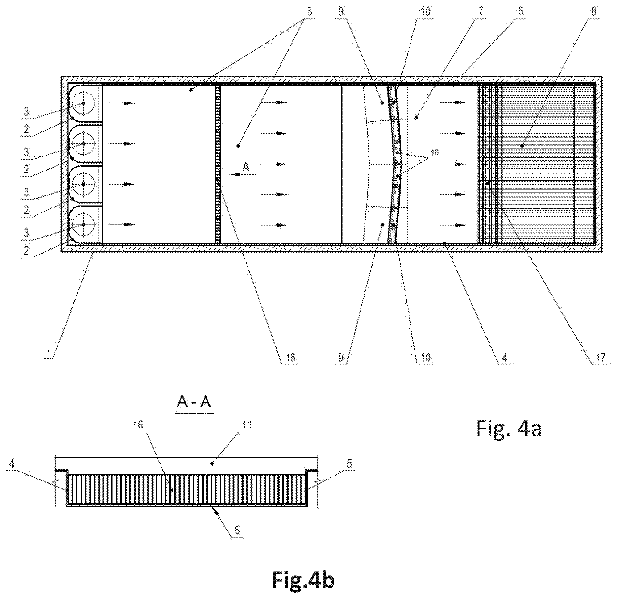
[0031]In the drawings: 1—reinforced concrete bowl (water tank), 2—water moving (lifting) machine (hydraulic unit with water injection nozzles), 3—submersible pump, 4—left-hand side of channel, 5—right-hand side of channel, 6—wave fetching portion of channel, 7—channel bottom, 8—drainage grille, 9—threshold, 10—lifting (wave forming) crest , 11—two tier central platform, 12—side initiating platform, 13—water level, 14—riding wave, 15—crest hoist, 16—partition with sections (flow stabilizer), 17—control plate on drainage grilles.

[0032]The artificial wave generation surfing facility includes a water tank 1 (ref. to FIG. 1, FIG. 2, and FIG. 3) having installed at its upper portion a working surface having inclined section 6, drainage grille 8 that may have control plates 17.

[0033]The facility further comprises a submersible pump 3 whose outlet is connected to a water moving (lifting) machine (hydraulic unit) 2 with the hydraulic unit outlet being positioned above the working surface.

[00...


PUM


Abstract

The invention relates to water amusement facilities generating artificial waves for surfing. The technical result is a simpler and lighter design and a shorter assembly and dismantling time along with the capability to control the water flow rate and to stabilize the flow. The above technical result is achieved by the proposed artificial wave generation surfing facility, including a water tank having installed at its upper portion: a working surface having an inclined section and a drainage grille; a submersible pump whose outlet is connected to a water moving device (hydraulic unit), with the hydraulic unit's outlet being positioned above the working surface, the working surface is laid over flooring with a wave generation threshold and the hydraulic unit's outlet is partitioned into sections, the hydraulic unit's outlet has a direct exit channel to the upper edge of the working surface inclined section, while the lower edge of the working surface inclined section makes a smooth transition to the wave generation threshold.

Description

FIELD OF THE INVENTION[0001]The invention relates to water amusement facilities producing artificial waves for surfing.BACKGROUND OF THE INVENTION[0002]One known design of an artificial wave generation surfing facility is described in U.S. Pat. No. 8,516,624 (published on 2013 Aug. 27). This prior art design has been chosen as the closest analog.[0003]The closest analogous artificial wave generation surfing facility comprises: a main pool; a wave pool; an inclined ramp whose bottom end extends down into the pool, a horizontally arranged flow section flow section connected at an outlet end thereof to an upper end of the ramp; at least one pump connected to an inlet end of the flow section by means of which water is conveyed from the main pool to the flow section; at least one adjustable guide device in the wave pool at a distance downstream from the lower end of the ramp, wherein the wave pool is positioned above the main pool, wherein the at least one pump unit, during operation, be...

Claims


Application Information

Patent Timeline
IPC IPC(8): E04H4/00A63G31/00
CPCE04H4/0006A63B69/0093A63G31/007
Inventor ABRAMOV, ALEKSANDR GENNAD'EVICH
Owner WAVEBOX LTD
Learn More