
Operating multiple fracturing pumps to deliver a smooth total flow rate transition

a technology of total flow rate and pump, which is applied in the direction of pump control, positive displacement liquid engine, fluid parameter, etc., can solve the problems of reducing the quality of fracturing job, affecting the success of pumping operations at a wellsite, and reducing the quality of downhole operations and/or efficiency, so as to reduce the effect of temporary dip or spik

Active Publication Date: 2021-12-02
SCHLUMBERGER TECH CORP
View PDF19 Cites 43 Cited by
  • Summary
  • Abstract
  • Description
  • Claims
  • Application Information

AI Technical Summary

Benefits of technology

The present invention introduces an apparatus and method for adjusting the cumulative pumping rate of multiple pump units in a pumping system. This is achieved by automatically offsetting any temporary dip or spike in the individual pumping rates of one unit by a predetermined temporary adjustment of another unit's pumping rate, to reduce the effects of such events on the overall pumping rate. The controller can communicate with each pump unit controller, allowing for individual adjustments to be made based on the coded instructions received from the controller. The technical effect of this invention is to improve the stability and efficiency of a pumping system, reducing the effects of temporary events on the overall pumping rate.

Problems solved by technology

Success of the pumping operations at a wellsite may be affected by many factors, such as efficiency, failure rates, and safety related to operation of the pumps.
Systematic high pressure and flow rate spikes and vibrations generated by the pumps may cause mechanical fatigue, wear, and / or other damage to the pumps, which may decrease pumping flow rates, quality of downhole operations, and / or efficiency.
For example, during a fracturing job, the flow rate of slurry that is being pumped directly affects pressure at the wellhead, and pressure spikes and dips formed by the fracturing pumps decrease quality of the fracturing job.
However, operating fracturing pumps manually by controlling transmissions (e.g., gear selection) and prime movers (e.g., throttles of motors / engines) does not lend itself to such pump control due.
Furthermore, the pumps may be constructed using different components and may have different levels of wear and tear, such that the pumps cannot be accurately controlled via the same transmission and prime mover settings.

Method used


Image

  • Operating multiple fracturing pumps to deliver a smooth total flow rate transition
  • Operating multiple fracturing pumps to deliver a smooth total flow rate transition
  • Operating multiple fracturing pumps to deliver a smooth total flow rate transition

Examples


Embodiment Construction

[0020]It is to be understood that the following disclosure provides many different embodiments, or examples, for implementing different features or combinations of features. Specific examples of components and arrangements are described below to simplify the present disclosure. These are merely examples and are not intended to be limiting. In addition, the present disclosure may repeat reference numerals and / or letters in the various examples. This repetition is for simplicity and clarity and does not in itself dictate a relationship between the various embodiments and / or configurations discussed.

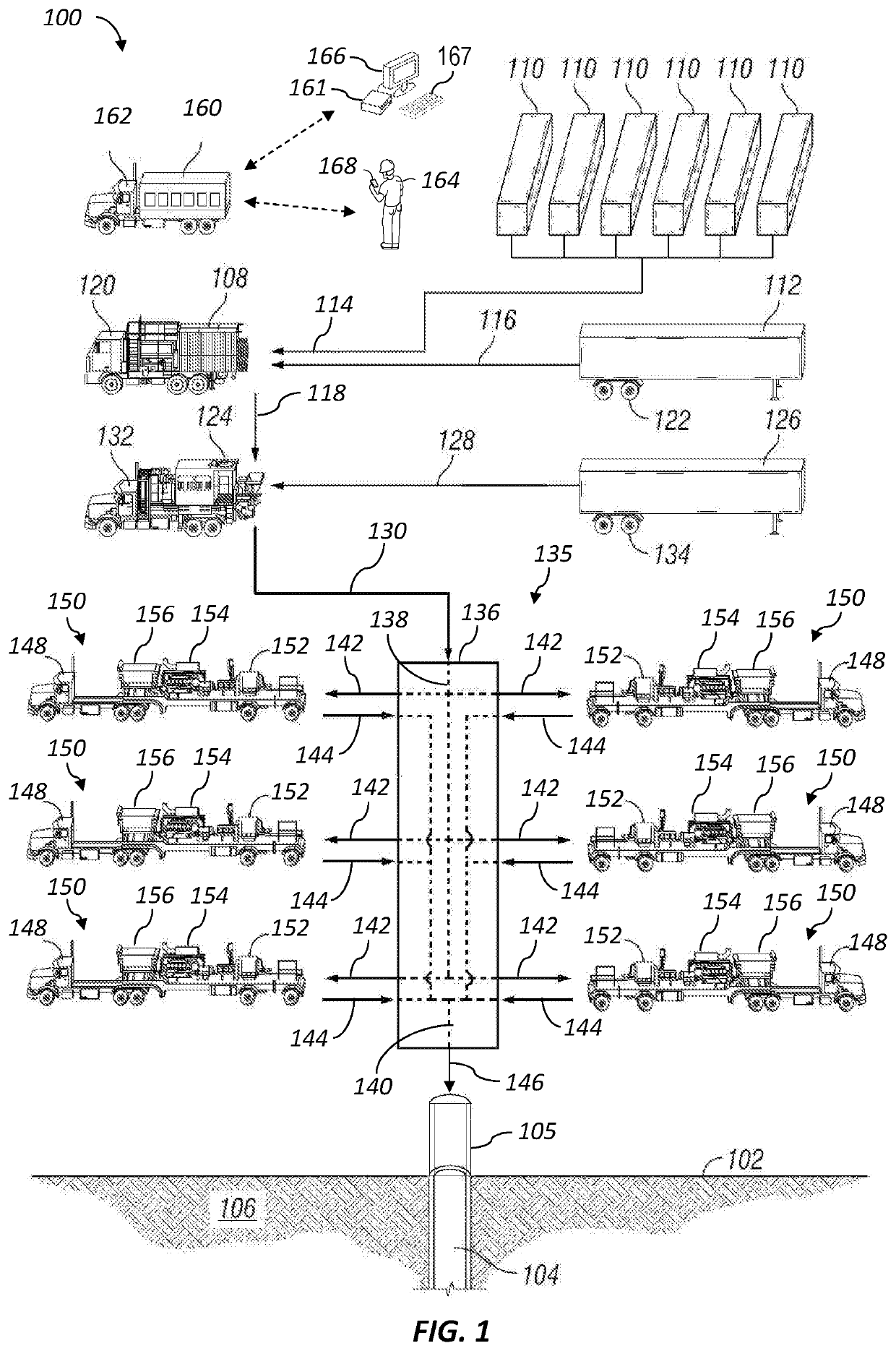
[0021]FIG. 1 is a schematic view of at least a portion of an example environment in which a control system according to one or more aspects of the present disclosure may be utilized. The figure shows a wellsite 102, a wellbore 104 extending from the terrain surface of the wellsite 102, a partial sectional view of a subterranean formation 106 penetrated by the wellbore 104, a wellhead 108, a...


PUM


Abstract

Changing a cumulative pumping rate of multiple pump units by adjusting individual pumping rates of the pump units, wherein each temporary dip or spike of an individual pumping rate of one of the pump units is automatically offset by a predetermined temporary adjustment of an individual pumping rate of another one or more of the pump units to thereby reduce effects of the temporary dip or spike on the cumulative pumping rate of the pump units.

Description

CROSS-REFERENCE TO RELATED APPLICATIONS[0001]This application claims priority to and the benefit of U.S. Provisional Application No. 62 / 620,663, titled “Operating Multiple Fracturing Pumps to Deliver a Smooth Total Flow Rate Transition,” filed Jan. 23, 2018, the entire disclosure of which is hereby incorporated herein by reference.BACKGROUND OF THE DISCLOSURE[0002]High-volume, high-pressure pumps are utilized at wellsites for a variety of pumping operations. Such operations may include drilling, cementing, acidizing, water jet cutting, hydraulic fracturing, and other wellsite operations. In some pumping operations, several pumps may be fluidly connected to a well via various fluid conduits and / or a manifold. During such operations, the fluid conduits and / or the manifold distributes low-pressure fluid from a mixer, a blender, and / or other sources among the pumps and combines pressurized fluid from the pumps for injection into the well. Success of the pumping operations at a wellsite ...

Claims


Application Information

Patent Timeline
Patent Type & Authority Applications(United States)
IPC IPC(8): F04B49/06F04B23/04F04B49/20
CPCF04B49/065F04B2205/09F04B49/20F04B23/04F04B1/06F04B1/053F04B41/06F04B2205/06
Inventor BAGULAYAN, AMALMU, NANMATTHEWS, JAMESMI, BAOTAYLOR, ALEXANDER TANNERKAJITA, MARCOS SUGURU
Owner SCHLUMBERGER TECH CORP
Features
  • Generate Ideas
  • Intellectual Property
  • Life Sciences
  • Materials
  • Tech Scout
  • Unparalleled Data Quality
  • Higher Quality Content
  • 60% Fewer Hallucinations
Learn More