Training a machine learning algorithm using digitally reconstructed radiographs

a machine learning algorithm and radiograph technology, applied in the field of computerimplemented methods of training likelihood-based computational models, can solve the problems of low degree of similarity, difficult training only on clinical data, and a lot of time, and achieve the effect of increasing the degree of similarity

Pending Publication Date: 2021-12-09
BRAINLAB
View PDF0 Cites 1 Cited by
  • Summary
  • Abstract
  • Description
  • Claims
  • Application Information

AI Technical Summary

Benefits of technology

[0050]Elastic fusion transformations (for example, elastic image fusion transformations) are for example designed to enable a seamless transition from one dataset (for example a first dataset such as for example a first image) to another dataset (for example a second dataset such as for example a second image). The transformation is for example designed such that one of the first and second datasets (images) is deformed, for example in such a way that corresponding structures (for example, corresponding image elements) are arranged at the same position as in the other of the first and second images. The deformed (transformed) image which is transformed from one of the first and second images is for example as similar as possible to the other of the first and second images. Preferably, (numerical) optimisation algorithms are applied in order to find the transformation which results in an optimum degree of similarity. The degree of similarity is preferably measured by way of a measure of similarity (also referred to in the following as a “similarity measure”). The parameters of the optimisation algorithm are for example vectors of a deformation field. These vectors are determined by the optimisation algorithm in such a way as to result in an optimum degree of similarity. Thus, the optimum degree of similarity represents a condition, for example a constraint, for the optimisation algorithm. The bases of the vectors lie for example at voxel positions of one of the first and second images which is to be transformed, and the tips of the vectors lie at the corresponding voxel positions in the transformed image. A plurality of these vectors is preferably provided, for instance more than twenty or a hundred or a thousand or ten thousand, etc. Preferably, there are (other) constraints on the transformation (deformation), for example in order to avoid pathological deformations (for instance, all the voxels being shifted to the same position by the transformation). These constraints include for example the constraint that the transformation is regular, which for example means that a Jacobian determinant calculated from a matrix of the deformation field (for example, the vector field) is larger than zero, and also the constraint that the transformed (deformed) image is not self-intersecting and for example that the transformed (deformed) image does not comprise faults and / or ruptures. The constraints include for example the constraint that if a regular grid is transformed simultaneously with the image and in a corresponding manner, the grid is not allowed to interfold at any of its locations. The optimising problem is for example solved iteratively, for example by means of an optimisation algorithm which is for example a first-order optimisation algorithm, such as a gradient descent algorithm. Other examples of optimisation algorithms include optimisation algorithms which do not use derivations, such as the downhill simplex algorithm, or algorithms which use higher-order derivatives such as Newton-like algorithms. The optimisation algorithm preferably performs a local optimisation. If there is a plurality of local optima, global algorithms such as simulated annealing or generic algorithms can be used. In the case of linear optimisation problems, the simplex method can for instance be used.

Problems solved by technology

Training only on clinical data is difficult as gathering data may take a lot of time, the data may be of low quality and has to be sorted and labeled for machine learning.

Method used


Image

  • Training a machine learning algorithm using digitally reconstructed radiographs
  • Training a machine learning algorithm using digitally reconstructed radiographs
  • Training a machine learning algorithm using digitally reconstructed radiographs

Examples


Embodiment Construction

[0007]In the following, a short description of the specific features of the present invention is given which shall not be understood to limit the invention only to the features or a combination of the features described in this section.

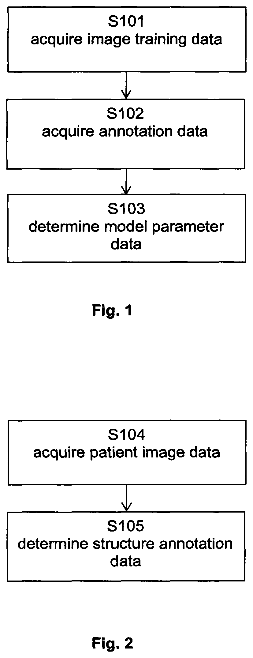
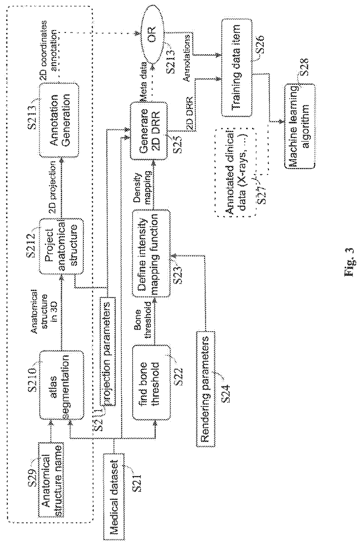
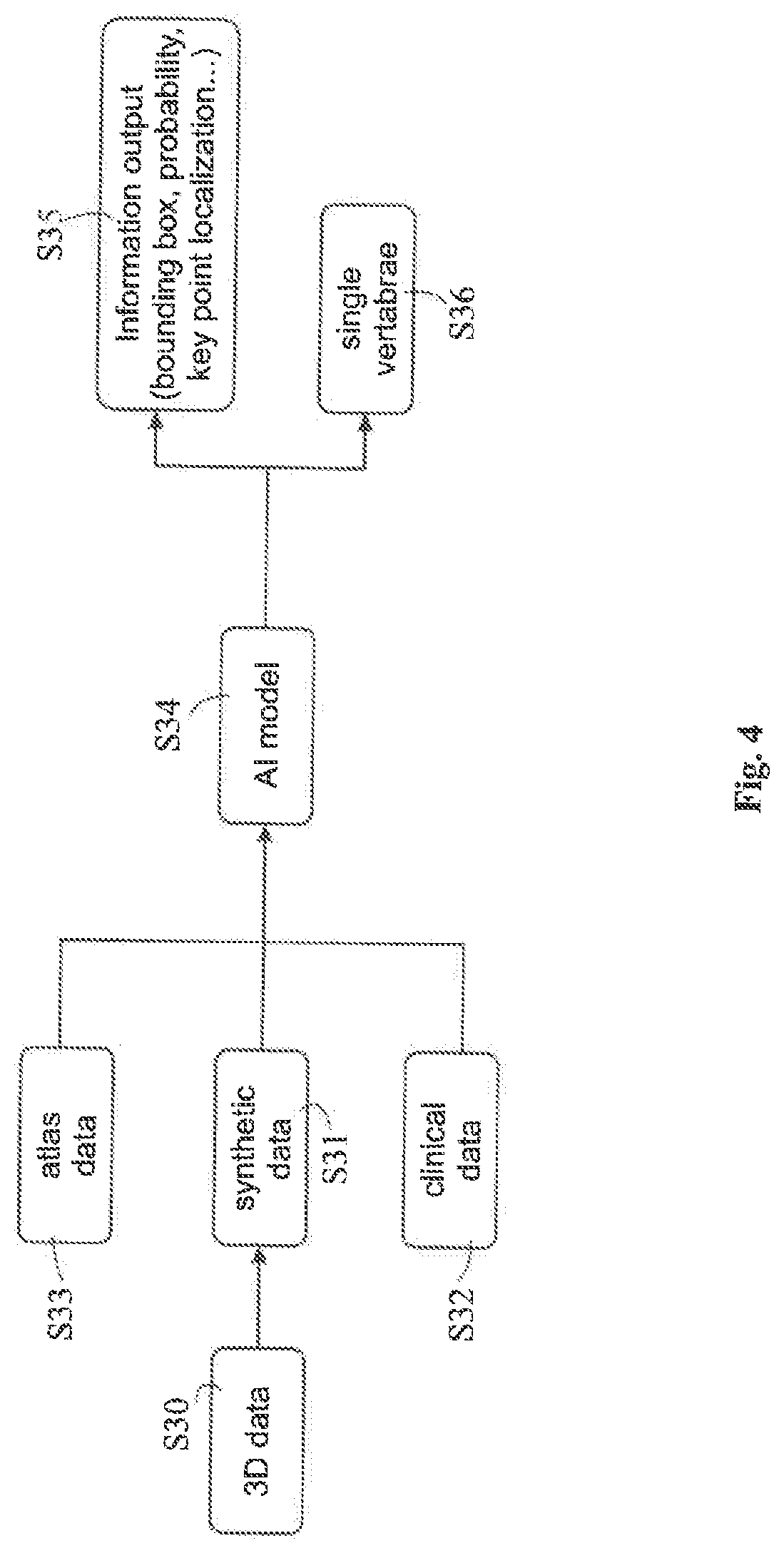
[0008]The disclosed method encompasses inputting medical DRRs together with annotation to a machine learning algorithm to train the algorithm, i.e. to generate adapted learnable parameters of the machine learning model. The annotations may be derived from metadata associated with the DRRs or may be included in atlas data which is matched with the DRRs to establish a relation between the annotations included in the atlas data and the DRRs. The thus generated machine learning algorithm may then be used to analyse clinical or synthesized DRRs so as to appropriately add annotations to those DRRs and / or identify the position of an anatomical structure in those DRRs.

General Description of the Invention

[0009]In this section, a description of the general feat...


PUM


Abstract

Disclosed is a computer-implemented method of training a likelihood-based computational model for determining the position of an image representation of an annotated anatomical structure in a two-dimensional x-ray image, wherein the method encompasses inputting medical DRRs together with annotation to a machine learning algorithm to train the algorithm, i.e. to generate adapted leamable parameters of the machine learning model. The annotations may be derived from metadata associated with the DRRs or may be included in atlas data which is matched with the DRRs to establish a relation between the annotations included in the atlas data and the DRRs. The thus generated machine learning algorithm may then be used to analyse clinical or synthesized DRRs so as to appropriately add annotations to those DRRs and / or identify the position of an anatomical structure in those DRRs.

Description

FIELD OF THE INVENTION[0001]The present invention relates to a computer-implemented method of training a likelihood-based computational model for determining the position of an image representation of an annotated anatomical structure in a two-dimensional x-ray image, a corresponding computer program, a computer-implemented method of determining a relation between an anatomical structure represented in a two-dimensional medical image and an annotation for the anatomical structure, a program storage medium storing such a program and a computer for executing the program, as well as a medical system comprising an electronic data storage device and the aforementioned computer.TECHNICAL BACKGROUND[0002]Training of machine learning algorithms using synthetic models has been used before. For example, the Microsoft Kinect was trained on 3D models which provided the labels per pose.[0003]The literature does not mention using digitally reconstructed radiographs (DRRs) for training algorithms ...

Claims


Application Information

Patent Timeline
Patent Type & Authority Applications(United States)
IPC IPC(8): G06T7/73G06N3/08G06N3/04G16H30/20G16H30/40G16H50/20G06T7/00
CPCG06T7/73G06N3/08G06N3/04G16H30/20G16H30/40G06T2207/20084G06T7/0012G06T2207/10121G06T2207/20081G06T2207/30004G16H50/20G06N3/084G16H50/70G06N3/045
Inventor LE, KIMMEURER, YANNICDREXL, THOMASFEILKAS, THOMAS
Owner BRAINLAB
Why Eureka
Try Eureka