Endoscopic instrument

a technology of endoscopic instruments and shank tools, applied in the field of endoscopic instruments, can solve the problems of not only being used therapeutically, but also merely diagnosing, and reducing the risk and achieving the effect of avoiding the danger of injury due to sharp-edged tool heads and being easy to position and actuate the shank tools by a single user

Pending Publication Date: 2021-12-16
RICHARD WOLF GMBH
View PDF0 Cites 0 Cited by
  • Summary
  • Abstract
  • Description
  • Claims
  • Application Information

AI Technical Summary

Benefits of technology

[0047]Further optionally, the shank connection part comprises guide devices for guiding pull wires. By way of guiding the pull wires, these can directly follow each rotation of the shank connection part. A crossing of the pull wires and of the associated slots in the sealing means can be prevented, so that the sealing effect is not compromised by way of this. The seal receiver can further be supplemented by a cover in the distal direction, said cover being away from the shank connection part and likewise being coupled to the shank connection part in a rotationally fixed manner. The cover can further likewise comprise guide devices, with which pull wires can be led. The guide devices in the cover and in the shank connection part are preferably flush, so that the sealing means experiences exclusively axial forces of the pull wires.
[0048]According to a further aspect of the present disclosure, concerning an endoscopic instrument which comprises a shank which can be coupled to a handling device, a shank tool, for example with a capture basket which is integrated therein or a forceps, can be pushed through a working channel of the instrument onto the distal end of the instrument. The handling device for this can preferably comprise a working channel inlet, a first rotatable receiving part and a second receiving part which is connected to the first receiving part in a rotationally fixed manner. The first receiving part can be fixedly coupled to a jacket element of the shank tool, for example via a Luer connection, nonetheless be displaceably mounted for the exact axial positioning relative to the working channel inlet. The second receiving part can be coupled to a distal tool head, for example a capture basket or forceps jaw parts, via a control wire which is led through the jacket element of the shank tool, and be axially displaceably mounted relative to the first receiving part. The shank tool can be pushed in the instrument into different axial positions through the first receiving part. By way of this, it is possible to insert the shank tool through the shank onto the distal shank tip in a positioned manner, so that it firstly does not project beyond it. The distal shank tip can consequently be moved to an operation region in an uninhibited manner and a danger of injury due to a sharp-edged tool head is avoided. After reaching the operational region, by way of displacing the first receiving part in the distal direction, the shank tool can be pushed out of the distal shank end. The wire which is coupled to the tool head, for example the capture basket or forceps jaw parts, as the case may be can then be subsequently pushed out of the jacket element of the shank tool by way of displacing the second receiving part. The shank tool can be rotated by way of a rotationally fixed coupling of the shank tool and of the first receiving part as well as a rotationally fixed coupling between the second receiving part and the first receiving part. By way of such a construction, furthermore it is very easily possible to position and actuate the shank tool by a single user. Coordination with a second user is consequently not necessary.

Problems solved by technology

Such uretero-renoscopes however can not only be used therapeutically, but also merely diagnostically, since the treating person can herewith view and diagnose the kidney tube or ureter in a direct manner.
A return of rinsing fluid at the outer side of the shank or through an additionally inserted auxiliary shank leads to an additionally expansion of the tissue and is disadvantageous with respect to a minimal invasive operation.
Furthermore, an overpressure can build up, such counteracting the flow of rinsing agent.

Method used


Image

  • Endoscopic instrument
  • Endoscopic instrument
  • Endoscopic instrument

Examples


Embodiment Construction

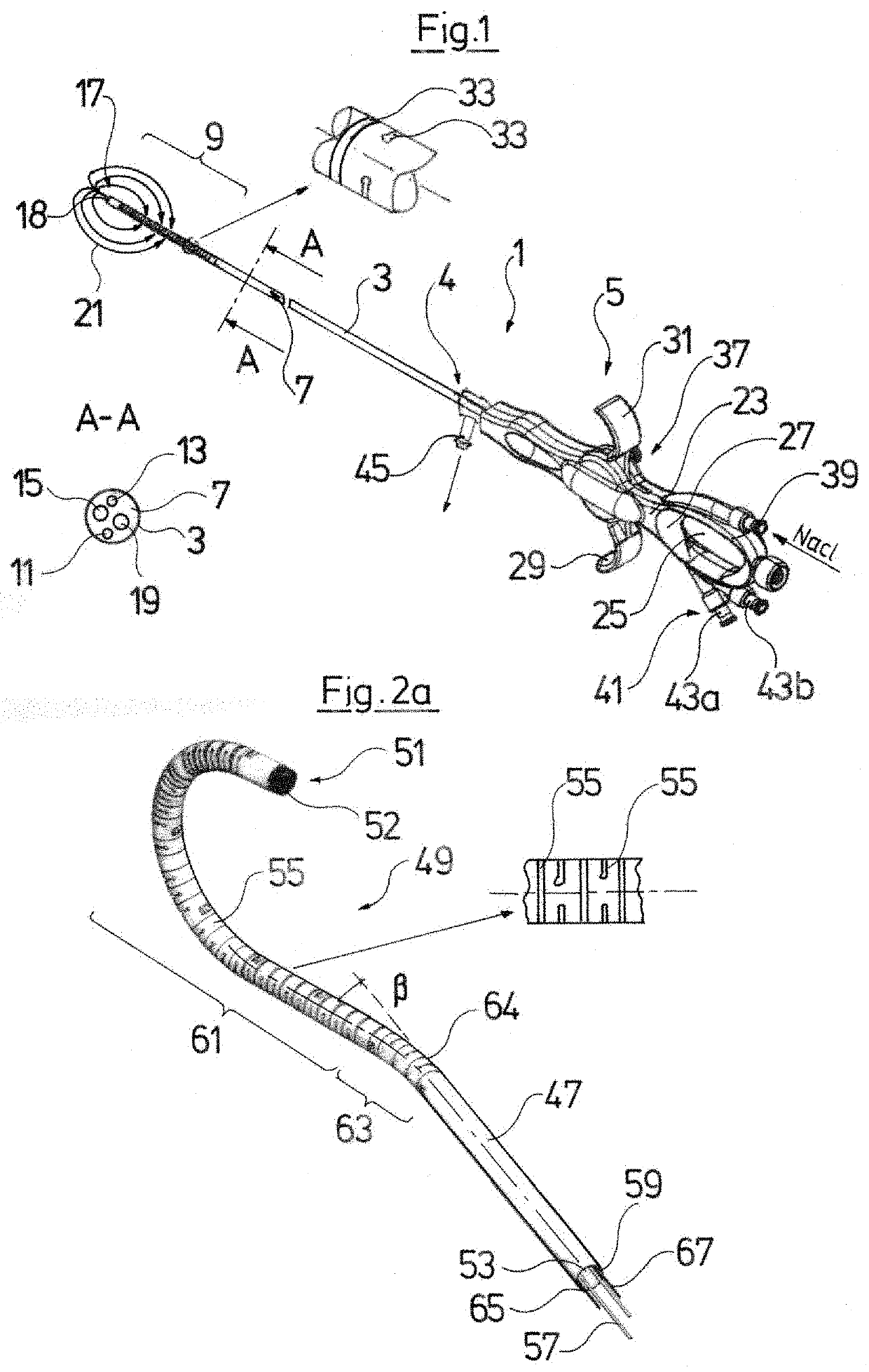
[0064]Referring to the drawings, FIG. 1 by way of example shows an endoscopic instrument 1 which comprises a tubular shank 3 for insertion into a body cavity. The shank 3 is connected to a handling device 5 at a proximal end 4 and in its inner lumen forms a fluid channel 7. The shank 3 furthermore at a distal, bendable shank section 9 is configured in at least partly flexible manner, in order when necessary to be bent by way of the action of the handling device 5.

[0065]It is evident in a part-section A-A through the shank 7 that by way of example a first optical and / or electrical lead 11 for the illumination at the distal shank end 17, a second optical and / or electrical lead 13 for taking pictures at the distal shank end 17, a first working channel 15 and a second working channel 19 run in the fluid channel 7. An LED as a light source can be arranged at the distal end of the first lead 11, wherein the lead 11 serves as an electrical electricity supply lead to the LED. Alternatively ...


PUM


Abstract

An endoscopic instrument (1, 134), for inserting into a body of a patient, includes a tubular shank (3, 47, 137) which is coupled or can be coupled to a handling device (5, 135) and is with a working channel (15). A shank tool can be led through the working channel (15). The working channel (15) includes a proximal working channel opening (153) for inserting the shank tool and a fluid inlet (148) which is separate from the proximal working channel opening.

Description

CROSS REFERENCE TO RELATED APPLICATIONS[0001]This application is a United States National Phase Application of International Application PCT / DE2019 / 200130, filed Nov. 7, 2019, and claims the benefit of priority under 35 U.S.C. § 119 of German Application 10 2018 218 954.4, filed Nov. 7, 2018, the entire contents of which are incorporated herein by reference.TECHNICAL FIELD[0002]The disclosure relates to an endoscopic instrument for inserting into a body of a patient, preferably as a disposable article for disposal after using once and preferably for the minimal-invasive diagnosis of kidney tubes and ureters as well as for the removal of kidney and urinary stones.TECHNICAL BACKGROUND[0003]The starting point of the invention are uretero-renoscopes as are known for instance from EP 2 986 237 B1. A shank of the uretero-renoscope is inserted into the body of a patient via the ureter, in order with a distal gripping means such as for instance a capture basket or a Dormia loop, to capture ...

Claims


Application Information

Patent Timeline
Patent Type & Authority Applications(United States)
IPC IPC(8): A61B17/221A61B17/00
CPCA61B17/221A61B17/00234A61B2017/0023A61B2017/22078A61B2017/00296A61B2017/00238A61B2017/2212A61B1/015A61B1/018A61B1/0056A61B1/00137A61B1/0052A61B1/0057A61B2017/0046A61B1/00103A61B1/00114A61B1/00117A61B1/00119A61B1/07
Inventor HEIMBERGER, RUDOLF
Owner RICHARD WOLF GMBH
Why Eureka
Try Eureka