In-vehicle sensor system

a sensor system and vehicle technology, applied in the field of vehicle sensors, can solve the problems of high-accuracy observation objects, difficult to accurately observe the whole area of the range to be observed, and long time-consuming to try to observe the situation around a vehicle widely and accurately, so as to quickly and efficiently recognize the situation around the vehicle, the effect of quick and reliable performan

Pending Publication Date: 2021-12-16
TOYOTA JIDOSHA KK
View PDF0 Cites 3 Cited by
  • Summary
  • Abstract
  • Description
  • Claims
  • Application Information

AI Technical Summary

Benefits of technology

[0004]Meanwhile, to realize driving assistance or autonomous driving more appropriately or more accurately, it is preferable to more accurately detect the situation around a vehicle, that is, it is preferable to more accurately detect the information on the presence or absence of persons, other vehicles, obstacles, and displays, etc. around the vehicle and the information on their positions or motions (moving speed, moving direction) and their types. In regard to this point, when the situation around a vehicle is observed using the in-vehicle sensor systems described above, the time required for observation becomes longer as the observation accuracy, that is, the observation resolution, becomes higher. Therefore, an attempt to observe the situation around a vehicle widely and accurately requires a long time. In particular, when a vehicle is travelling, the observation is made while moving. This means that the time that can be spent on observing a particular range is limited and, therefore, it is sometime temporarily difficult to accurately observe the whole area of a range to be observed. To address this problem, the present applicants propose an in-vehicle sensor system (Japanese Patent Application No. 2020-71587.) This in-vehicle sensor system uses two sensors: a first sensor (coarse observation sensor) that detects the situation around a vehicle and a second sensor (fine observation sensor) that has an angular resolution higher than that of the first sensor. In the configuration of this in-vehicle sensor system, the situation around a vehicle is widely and quickly observed at a relatively low resolution by the coarse observation sensor. After that, by referring to the observation result of the coarse observation sensor, an area in which an object to be observed accurately (high-accuracy observation object) is included is identified in that observation range and, then, the identified area is observed at a high resolution by the fine observation sensor. According to this in-vehicle sensor system, the coarse observation sensor is used to quickly observe the wide range around the vehicle and, then, the fine observation sensor is used to observe a narrowed area including an object to be observed relatively accurately. This configuration makes it possible to obtain an accurate observation result for a particular area for which accurate information is desired while reducing the total observation time.

Problems solved by technology

Therefore, an attempt to observe the situation around a vehicle widely and accurately requires a long time.
This means that the time that can be spent on observing a particular range is limited and, therefore, it is sometime temporarily difficult to accurately observe the whole area of a range to be observed.
In that case, when the high-accuracy observation object or the vehicle itself moves from the time the observation by the coarse observation sensor is performed to the time the observation by the fine observation sensor is started, the high-accuracy observation object deviates from the area identified in the range observed by the coarse observation sensor and, as a result, the high-accuracy observation object cannot be observed by the fine observation sensor.
In this case, even if the observation by the second sensor is performed in the presence position or range of the high-accuracy observation object identified at the time of observation by the first sensor, the high-accuracy observation object cannot be observed.

Method used


Image

  • In-vehicle sensor system
  • In-vehicle sensor system
  • In-vehicle sensor system

Examples


Embodiment Construction

Configuration of In-Vehicle Sensor System

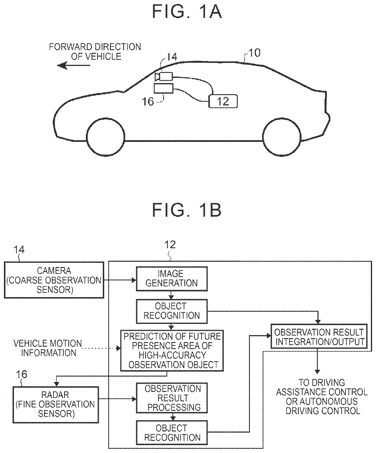
[0026]With reference to FIG. 1A, an embodiment of an in-vehicle sensor system of the present disclosure will be described. A vehicle 10 such as an automobile includes a coarse observation sensor 14, a fine observation sensor 16, and an observation control device 12. The coarse observation sensor 14 observes the situation around the vehicle 10 at a first resolution. The fine observation sensor 16 observes the situation around the vehicle 10 at a second resolution that is higher than the first resolution. The observation control device 12 controls the operation of the coarse observation sensor 14 and the fine observation sensor 16. In addition, the observation control device 12 receives signals from the coarse observation sensor 14 and the fine observation sensor 16 and, from the received signals, detects and recognizes the presence or absence of objects (such as other vehicles, roadside buildings, walls, fences, guardrails, poles, parked vehic...


PUM


Abstract

A system of the present disclosure includes a coarse observation sensor configured to observe a range around a vehicle, high-accuracy observation object identification means configured to identify a high-accuracy observation object that is an object detected by the coarse observation sensor in the observation range and is an object to be observed at a higher resolution, object presence area prediction means configured to predict a range of an object future presence area where the high-accuracy observation object may be present after the identification, a fine observation sensor configured to observe the range of the object future presence area at the higher resolution, and object information output means configured to output information on the high-accuracy observation object observed by the fine observation sensor.

Description

CROSS-REFERENCE TO RELATED APPLICATION[0001]This application claims priority to Japanese Patent Application No. 2020-103715 filed on Jun. 16, 2020, incorporated herein by reference in its entirety.BACKGROUND1. Technical Field[0002]The present disclosure relates to a device for detecting the situation around a vehicle such as an automobile, and more specifically to a system for observing the situation around the vehicle using sensors (camera, millimeter wave radar, lidar (laser radar) etc.) that are mounted on the vehicle for detecting persons, other vehicles, obstacles, and the like around the vehicle.2. Description of Related Art[0003]When driving assistance control or autonomous driving control is performed for a vehicle, it is necessary to recognize the situation around the vehicle (for example, the presence or absence and the positions of persons, other vehicles, obstacles, displays, etc.) In a vehicle that performs such control, a system (in-vehicle sensor system) is mounted th...

Claims


Application Information

Patent Timeline
Patent Type & Authority Applications(United States)
IPC IPC(8): B60W30/095G01S13/931G01S13/42
CPCB60W30/0956G01S13/931G01S13/42B60W30/0953B60W2554/20B60W2420/52B60W2520/00B60W2554/4029G01S2013/9323B60W60/0027B60W2554/402B60W2552/53G01S2013/932G01S13/867G01S2013/93276G01S2013/93271G01S17/86G01S17/931G01S2013/9318G01S2013/93185G01S2013/9319
Inventor KOBAYASHI, TAKUMI
Owner TOYOTA JIDOSHA KK
Why Eureka
Try Eureka