One-way air outlet channel for vacuum compression bag and vacuum compression bag having one-way air outlet channel

a vacuum compression bag and one-way technology, applied in the field of vacuum compression bags, can solve the problems of unfavorable use, unfavorable vacuuming process, high cost, etc., and achieve the effects of easy operation, low cost and increased difficulty in vacuuming

Active Publication Date: 2021-12-23
ZHONGSHAN TAILI HOUSEHOLD PROD MFG
View PDF0 Cites 0 Cited by
  • Summary
  • Abstract
  • Description
  • Claims
  • Application Information

AI Technical Summary

Benefits of technology

[0037]1. With the one-way air outlet channel of the invention, after the vacuum compression bag is filled with objects, it is only necessary to seal the bag opening and press the vacuum compression bag, and then the air inside the bag body can be expelled to the outside through the one-way air outlet channel. The one-way air outlet channel and the bag body are vacuumed and sealed by being squeezed and deformed under the effect of pressure difference inside and outside the bag. There is no need to use a vacuum air outlet pump, the operation is easy and the cost is low.
[0038]2. The one-way air outlet channel of the invention includes at least two corner points. When air flows through the one-way air outlet channel, the flowing direction of the air at least changes twice, thereby effectively increasing the difficulty for the air from the outside to enter the bag body through the one-way air outlet channel, and the vacuum compression bag can therefore maintain in the vacuum state.
[0039]3. When the vacuum compression bag is squeezed and compressed and deformed, due to the relatively large degree of space freedom at the corners of the bag, the corners of the bag are less affected after the bag body is compressed and deformed. Therefore, the one-way air outlet channel arranged at the corner of the bag body is less likely to be blocked immediately when the bag body is deformed, thereby ensuring that the air inside the vacuum compression bag can be smoothly expelled to the outside.
[0040]4. In the invention, the air inlet opening is arranged to face the center of the top portion / or bottom portion of the vacuum compression bag body. In the air expelling process of the vacuum compression bag, since the air inside the bag is mainly distributed at the top portion or bottom portion of the bag body, through such design, the air can be expelled to the outside of the bag body more quickly.
[0041]5. When the air outlet opening of the invention is located at the lateral portion of the bag body away from the corner of the bag body, the position near the junction A makes the air channel to open easily when the bag body is compressed to expel air, and the air is likely to flow back, which affects the sealing effect. Therefore, by arranging the air outlet opening at the lateral portion of the bag body or a position at the bottom portion near the corner, it is possible to effectively prevent the junction A of the vacuum compression bag from being broken in the process of pressing and expelling air.
[0042]6. The diameters of the air inlet opening, the horizontal air channel, the inclined air channel, the vertical air channel and the air outlet opening range from 20 to 60 mm. The diameters within this range can make the one-way air outlet channel to achieve an ideal air-expelling effect.

Problems solved by technology

Therefore, it is not user friendly in terms of convenience.
If the user chooses to buy an electric vacuum air outlet pump, which is undoubtedly a large additional financial burden for the consumer.
If the user uses a cheap manual vacuum air outlet pump to achieve the vacuuming purpose, the vacuuming process takes a lot of time and efforts.
Besides, the air expelling efficiency is low, especially for vacuuming some vacuum bags with a large size, the air expelling efficiency will be lower, and it takes much more time to expel the air.
However, during the research and development process, it was found that many types of one-way air outlet channels have unsatisfactory air expelling effect and / or air leakage.
Therefore, the one-way air outlet channel cannot ensure the airtightness in the bag body.
In addition, with the negative pressure effect of the sealed bag body, it is difficult for air to flow back to the bag body through the one-way air outlet channel.
When air flows through the one-way air outlet channel, the flowing direction of the air at least changes twice, thereby effectively increasing the difficulty for the air from the outside to enter the bag body through the one-way air outlet channel, and the vacuum compression bag can therefore maintain in the vacuum state.

Method used


Image

  • One-way air outlet channel for vacuum compression bag and vacuum compression bag having one-way air outlet channel
  • One-way air outlet channel for vacuum compression bag and vacuum compression bag having one-way air outlet channel
  • One-way air outlet channel for vacuum compression bag and vacuum compression bag having one-way air outlet channel

Examples


embodiment 1

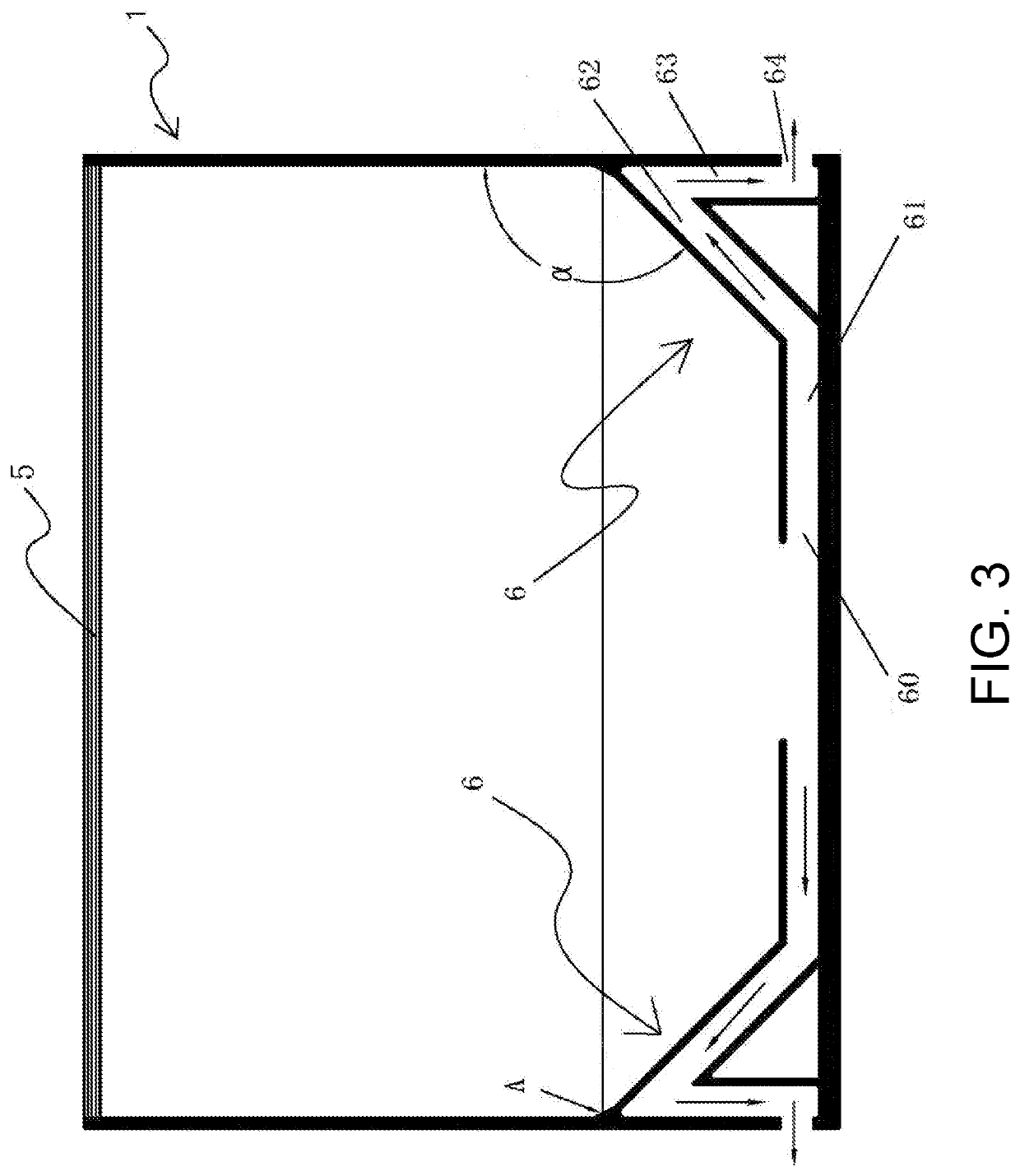
[0060]As shown in FIG. 3, the one-way air outlet channel 6 is arranged in a vacuum compression bag. The one-way air outlet channel 6 includes a horizontal air channel 61, an inclined air channel 62, and a vertical air channel 63 that are in communication in sequence. A first corner point is formed at the position where the horizontal air channel 61 and the inclined air channel 62 are connected. A second corner point is formed at the position where the inclined air channel 62 is connected with the top end of the vertical air channel 63. An air inlet opening 60 is provided at one end of the horizontal air channel 61 away from the inclined air channel 62. An air outlet opening 64 is provided on the bag body of the vacuum compression bag. The bottom end of the vertical air channel 63 is in communication with the air outlet opening 64.

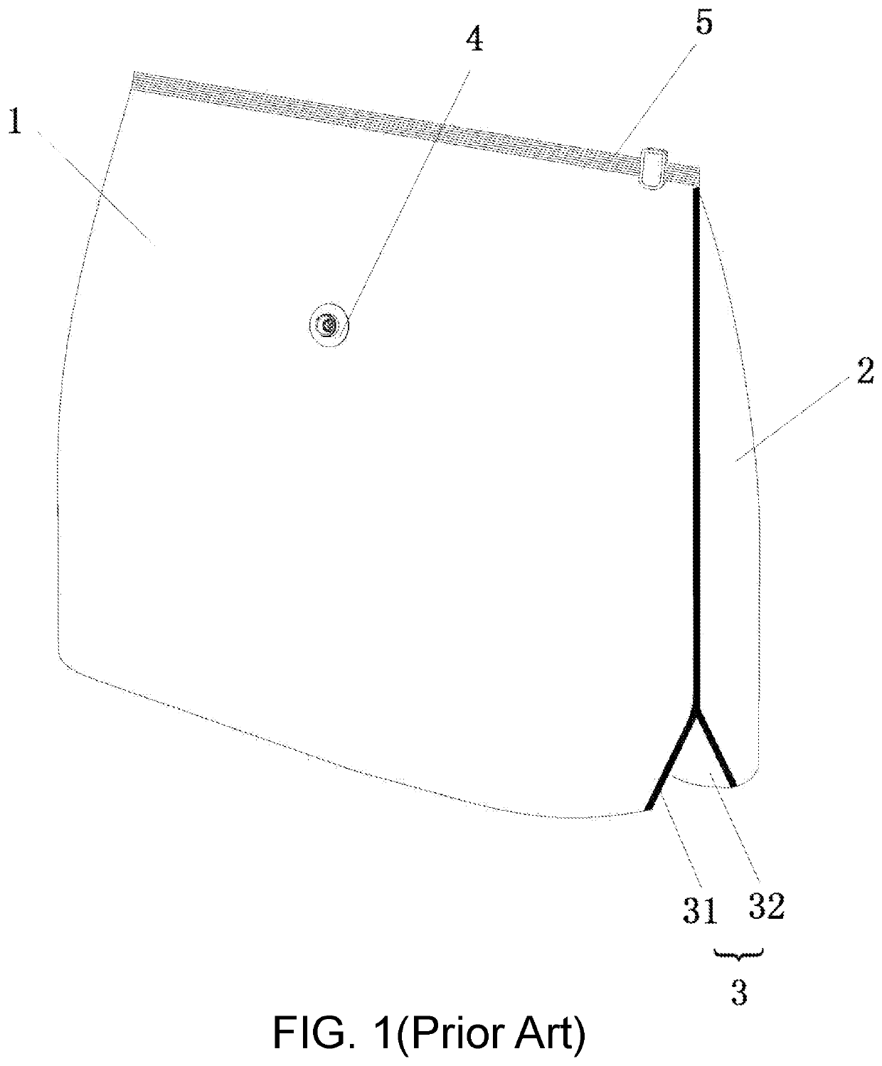
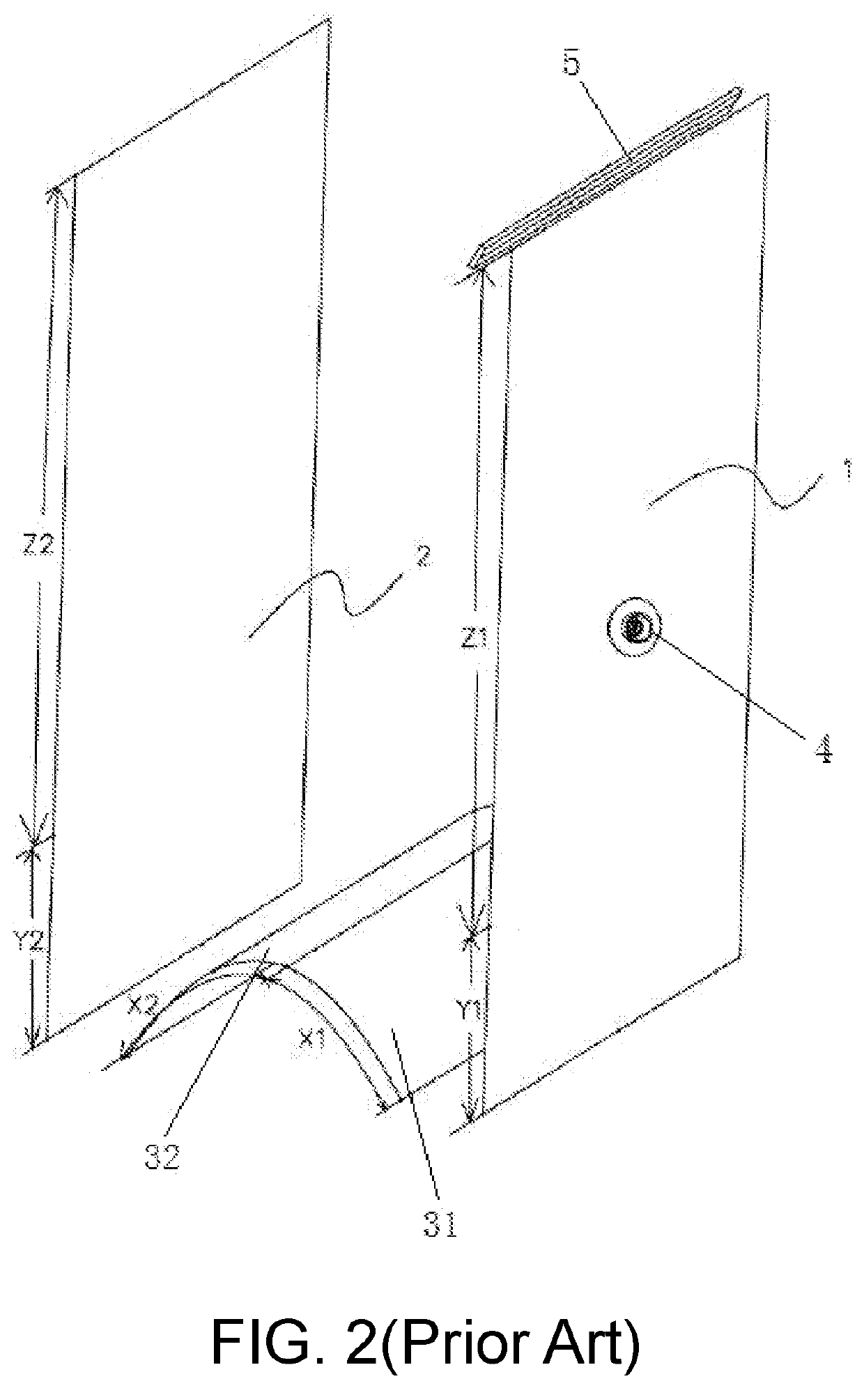
[0061]The vacuum compression bag is a vacuum compression bag with a split structure on a bag body, and the split structure is located at the bottom portion...

embodiment 2

[0065]As shown in FIG. 4, the difference between the embodiment 2 and the embodiment 1 is as follows.

[0066]The one-way air outlet channel 6 is further provided with an arc-shaped hot press block 7, which is specifically located at the position where the obtuse angle α is formed between the inclined air channel 62 and the third lateral side, such that the arc-shaped hot press block 7 can be used to disperse the stress concentrated here in the process of pressing and expelling air.

[0067]A junction A is formed between the first lateral side, the second lateral side and the third lateral side. The distance between the horizontal tangent of the arc-shaped hot press block 7 and the junction A is d, and d ranges from 5 to 20 mm. With the distance within this range, a good tear-proof effect can be achieved.

embodiment 3

[0068]As shown in FIG. 5, the difference between the embodiment 3 and the embodiment 2 is as follows.

[0069]The horizontal air channel 61 includes a first horizontal air channel 611 and a second horizontal air channel 612. The first horizontal air channel 611 and the second horizontal air channel 612 are in communication with each other. A corner point is formed between the first horizontal air channel 611 and the second horizontal air channel 612, so that the horizontal air channel 61 forms a U-shaped structure. The air inlet opening 60 is located at one end of the first horizontal air channel 611 away from the second horizontal air channel 612, and one end of the second horizontal air channel 612 away from the first horizontal air channel 611 is in communication with the inclined air channel 62.

[0070]With the one-way air outlet channel 6 designed in this way, the number of corner points increases from two to four. The air from the outside must change flowing direction four times in...


PUM


Abstract

A one-way air outlet channel is disposed inside a vacuum compression bag. The one-way air outlet channel includes an air inlet opening, a horizontal air channel, inclined air channel and vertical air channel and an air outlet opening communication with one another in sequence. One end of the horizontal air channel is the air inlet opening in communication with a space inside the bag body, and the other end of the horizontal air channel is in communication with the inclined air channel. A bottom end of the vertical air channel is in communication with the air outlet opening, and a top end is in communication with the inclined air channel, such that at least two corner points are formed, at a location where the horizontal air channel connects the inclined air channel and at a location where the inclined air channel connects the vertical air channel.

Description

BACKGROUNDTechnical Field[0001]The invention relates to the field of vacuum compression bags, in particular to a one-way air outlet channel for vacuum compression bag and a vacuum compression bag having the one-way air outlet channel.Description of Related Art[0002]Conventional vacuum compression bag is equipped with a vacuum air outlet valve. As shown in FIG. 1 to FIG. 2, a conventional vacuum compression bag is characterized by the split at the lower part of the bag body, which can make the bag body stand upright. The vacuum compression bag includes a front bag panel 1, a rear bag panel 2, and a bottom bag panel 3. The bottom bag panel 3 is connected to the lower part of the bag body formed by the front bag panel 1 and the rear bag panel 2, thereby forming a Y-shaped split structure at the lower part of the bag body.[0003]Specifically, the rear bag panel 3 is divided into a first bottom surface 31 and a second bottom surface 32 by a fold line. The outer edge of the first bottom su...

Claims


Application Information

Patent Timeline
Patent Type & Authority Applications(United States)
IPC IPC(8): B65D33/01B65D81/20B65D33/25
CPCB65D33/01B65D2205/02B65D33/2584B65D81/2023B65D2205/00
Inventor SHI
Owner ZHONGSHAN TAILI HOUSEHOLD PROD MFG
Why Eureka
Try Eureka