Wearable display device

a display device and wearable technology, applied in the field of wearable display devices, can solve the problems of severely affecting the efficiency of the processing chip, and achieve the effect of improving the operation efficiency of the microprocessor chip and performing the heat dissipation function quietly

Active Publication Date: 2021-12-23
MICROJET TECH
View PDF3 Cites 2 Cited by
  • Summary
  • Abstract
  • Description
  • Claims
  • Application Information

AI Technical Summary

Benefits of technology

[0004]One object of the present disclosure is to provide a wearable display device. In the wearable display device according to one or some embodiments of the present disclosure, the heat dissipation processing module construed by the first actuator of the micro pump can perform heat dissipation effectively for the microprocessing chip inside the wearable display device so as to improve the operation efficiency of the microprocessing chip. Hence, the entire device may be miniaturized and can perform the heat dissipation function quietly. Moreover, the second actuator of the micro pump is provided for inflating the fillable gas bag, so that the wearable display device can provide wearing comfortableness even when the wearable display device is worn by the user for a long time. Furthermore, the third actuator of the micro pump and the intraocular pressure detector are provided for detecting the intraocular pressure of the user, so as to provide a notification to prevent the user from feeling dizzy or from having excessive intraocular pressure and cause damages for the user or affect the health for the user.

Problems solved by technology

However, it is understood that, the efficiency of the processing chip will be severely affected if the heat generated during the operation of the processing chip cannot be removed quickly.
Furthermore, it should be noted that the wearing comfortableness has to be considered since a user may wear and operate the wearable device for a long time.

Method used


Image

  • Wearable display device
  • Wearable display device
  • Wearable display device

Examples


Embodiment Construction

[0034]The present disclosure will now be described more specifically with reference to the following embodiments. It is to be noted that the following descriptions of different embodiments of this disclosure are presented herein for purpose of illustration and description only, and it is not intended to limit the scope of the present disclosure.

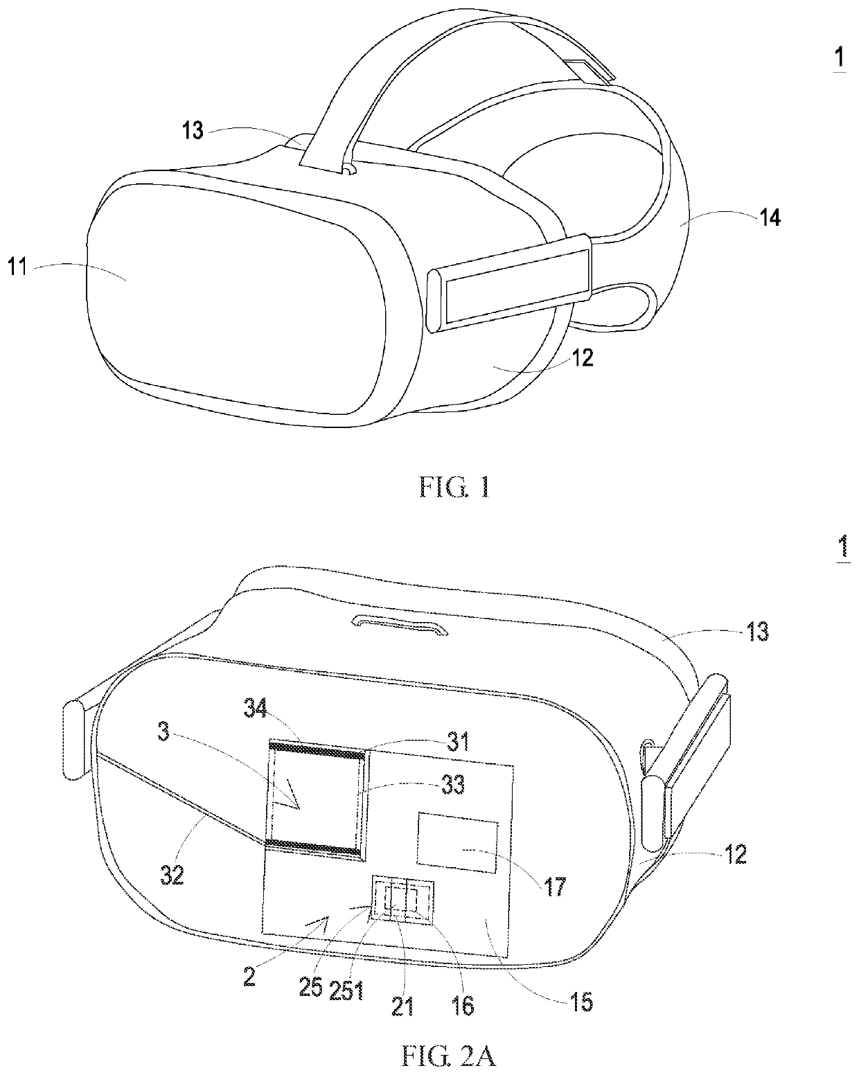
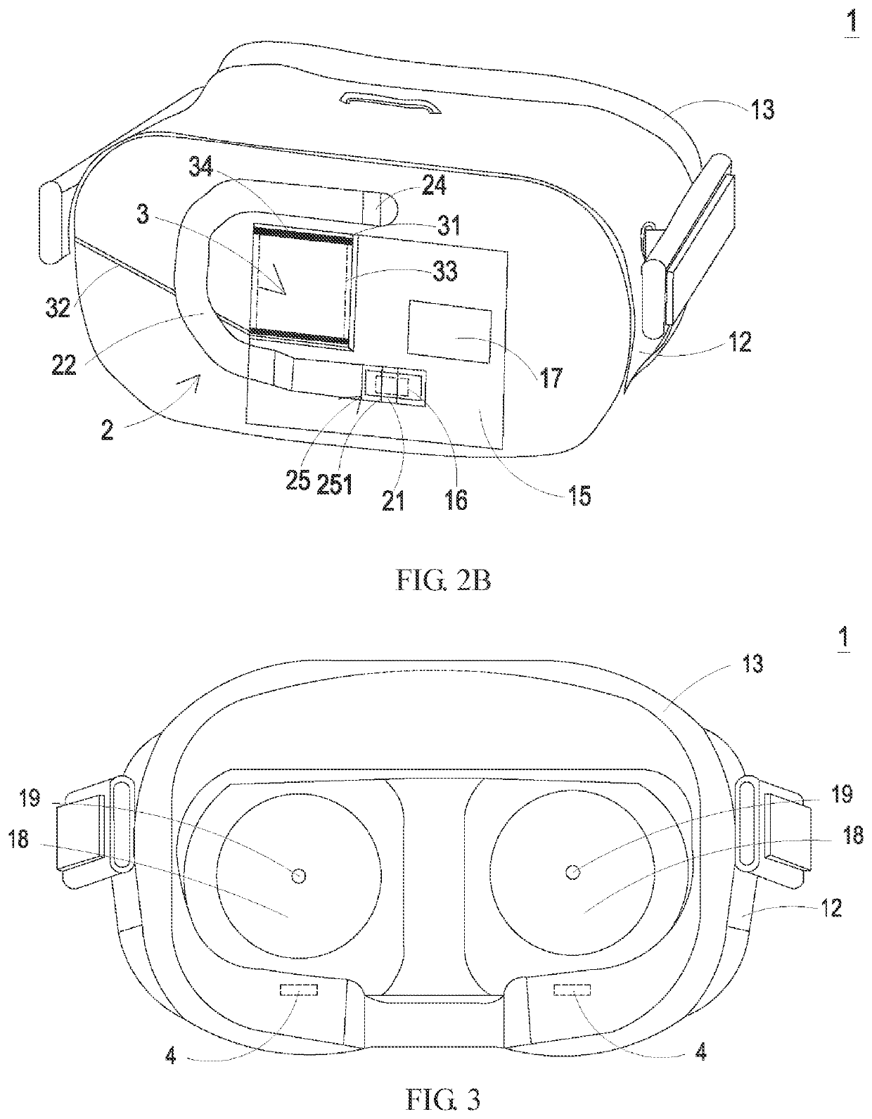
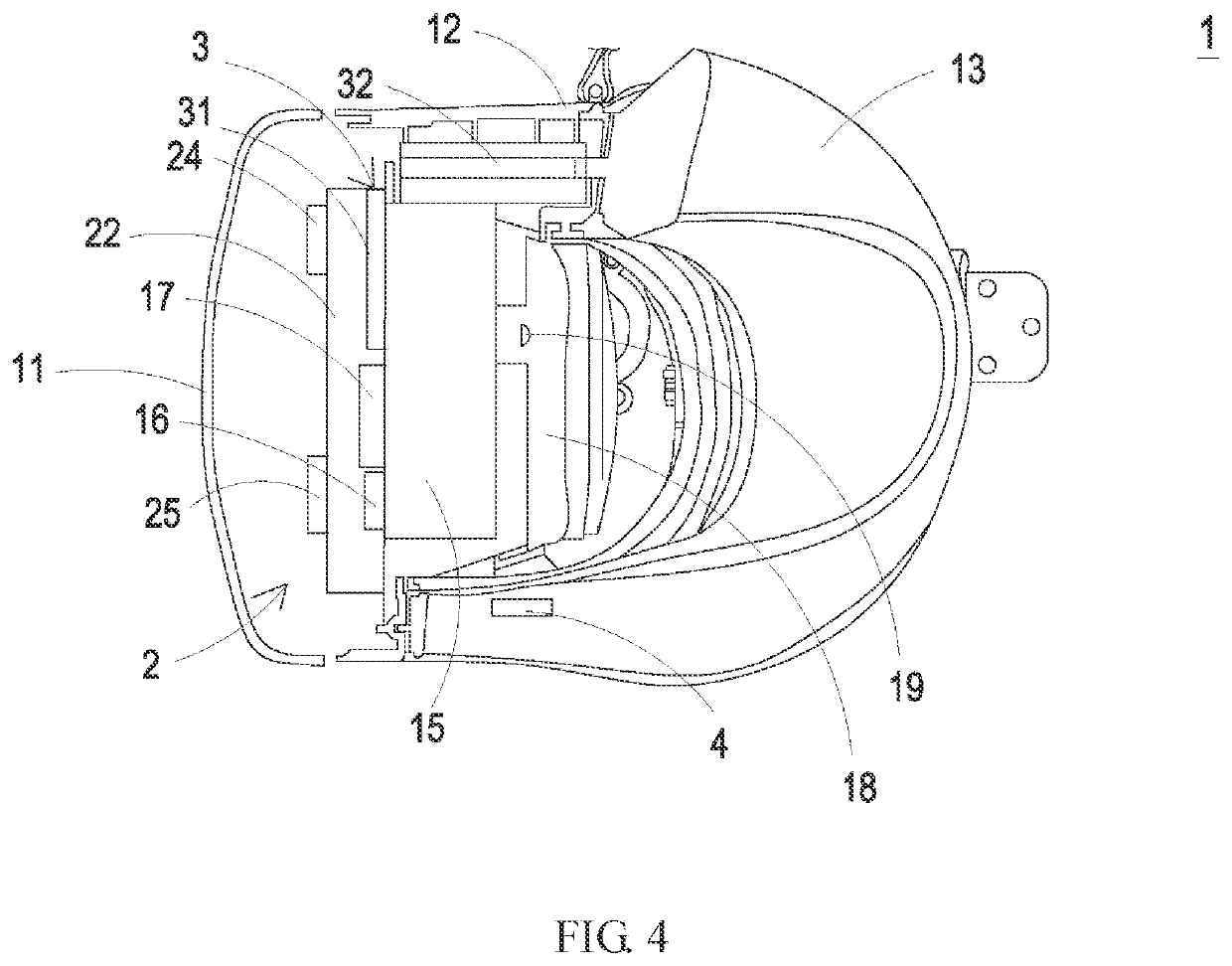
[0035]Please refer to FIG. 1 to FIG. 4. According to one or some embodiments of the present disclosure, a wearable display device including a device body 1, a heat dissipation module 2, and an inflation actuation module 3 is provided. The device body 1 includes a front cover 11, a side cover 12, a fillable gas bag 13, a head belt 14, a circuit board 15, a microprocessor 16, a communication device 17, and a display assembly 18. The side cover 12 is connected to one side of the front cover 11. The fillable gas bag 13 is attached to and positioned on one side of the side cover 12. The display assembly 18 is disposed and positioned on one side of...


PUM


Abstract

A wearable display device includes a device body, a heat dissipation processing module, and an inflation actuation module. The device body includes a front cover, a side cover, a fillable gas bag, a circuit board, and a microprocessor. The heat dissipation processing module includes a first actuator corresponding to the microprocessor for performing heat exchange for the microprocessor. The inflation actuation module includes a base member, a gas communication channel, a second actuator, and a valve component. When the second actuator and the valve component are driven, the valve component is opened to control gas introduction of the second actuator, and the second actuator is actuated to transmit the gas to the gas communication channel for gas collection, and the second actuator further transmits the gas to the fillable gas bag for inflating the fillable gas bag, so as to allow a user to wear the wearable display device stably.

Description

CROSS-REFERENCE TO RELATED APPLICATION[0001]This non-provisional application claims priority under 35 U.S.C. § 119(a) to Patent Application No. 109120890 filed in Taiwan, R.O.C. on Jun. 19, 2020, the entire contents of which are hereby incorporated by reference.BACKGROUNDTechnical Field[0002]The present disclosure relates to a wearable display device. In particular, to a head-wearable device that is capable of performing heat dissipation, gas inflation, and intraocular pressure detection.Related Art[0003]In recent years, owing to the quick developments of technologies, the specifications, the equipment, and the functions of devices related to virtual reality have been upgraded rapidly. In order to satisfy the needs of these devices, the ability of the processing chip inside a wearable display device is also upgraded. However, it is understood that, the efficiency of the processing chip will be severely affected if the heat generated during the operation of the processing chip cannot...

Claims


Application Information

Patent Timeline
Patent Type & Authority Applications(United States)
IPC IPC(8): G02B27/01H05K7/20G06F1/20B81B7/00G06F1/16
CPCG02B27/0176H05K7/2099G06F1/203B81B2201/036G06F1/206G06F1/163B81B7/0093
Inventor MOU, HAO-JANHSUEH, TA-WEICHEN, YU-TZUCHENG, SHOU-CHENGHUANG, CHI-FENGHAN, YUNG-LUNGLIN, TSUNG-I
Owner MICROJET TECH
Why Eureka
Try Eureka