
Lock structure of connector assembly

a technology of connector assembly and lock structure, which is applied in the direction of electrical apparatus, connection, and coupling device connection, etc., can solve the problems of reducing the size of the connector inside various electronic products, and reducing the overall mounting force of the connector, so as to improve the simplicity and intuition of operation and improve the effect of smooth operation

Active Publication Date: 2021-12-23
ACES ELECTRONICS CO LTD
View PDF0 Cites 0 Cited by
  • Summary
  • Abstract
  • Description
  • Claims
  • Application Information

AI Technical Summary

Benefits of technology

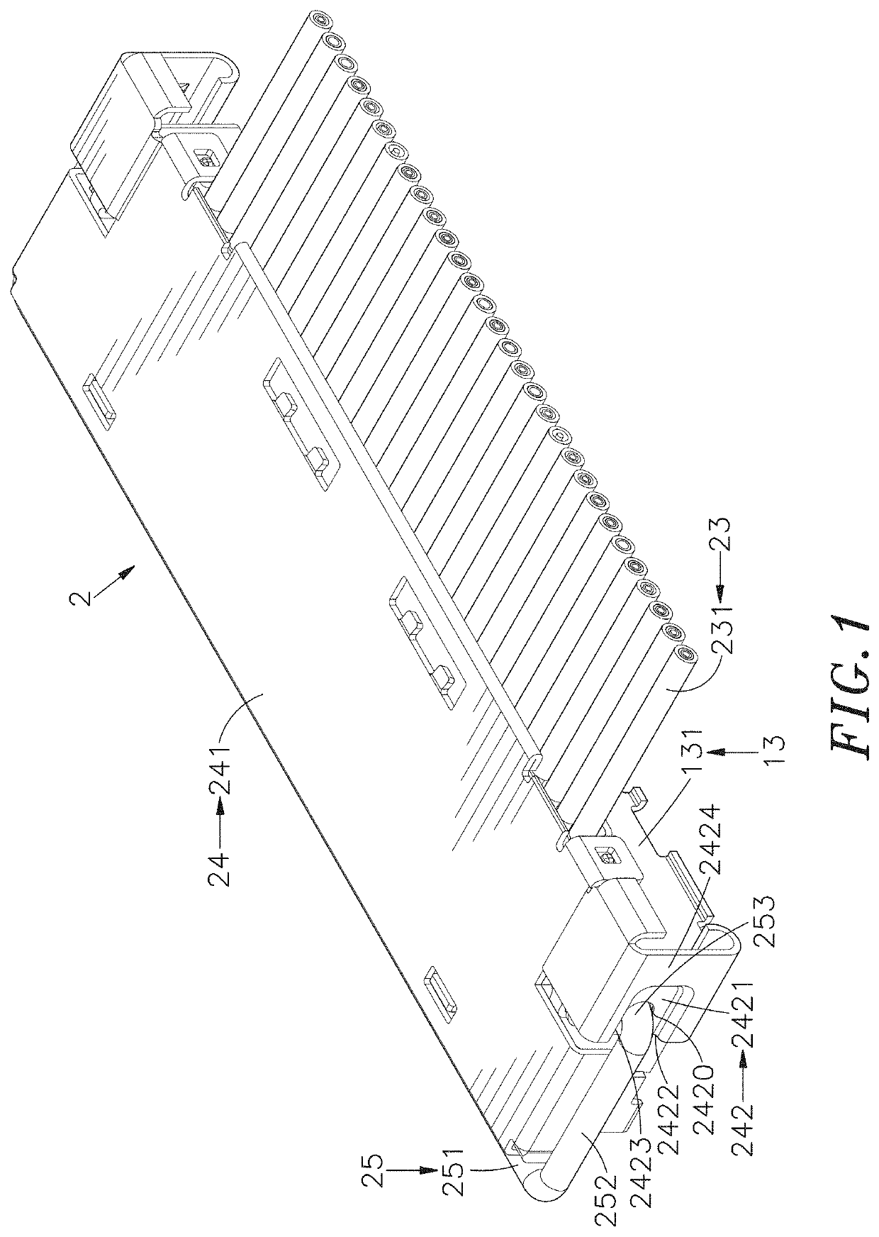
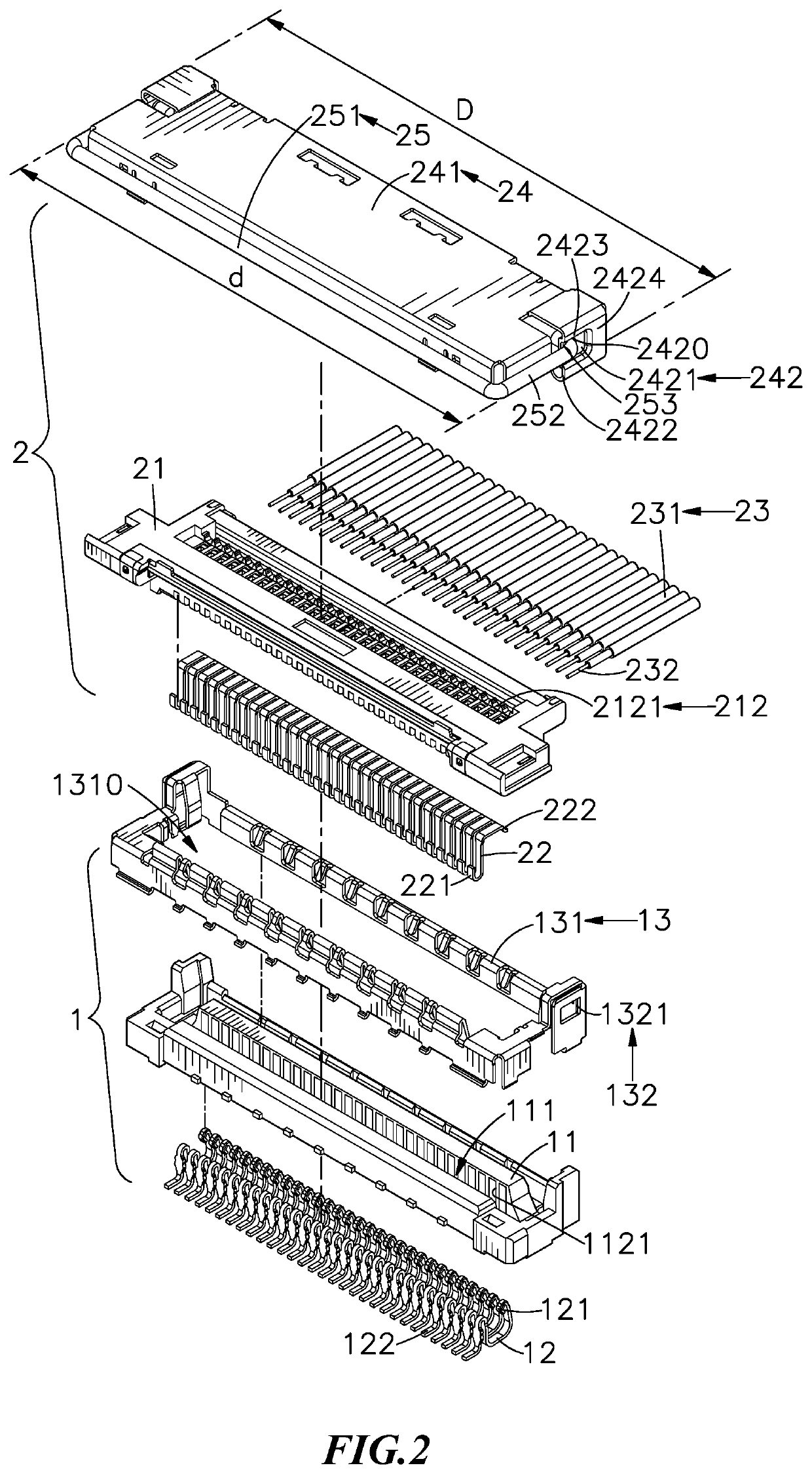
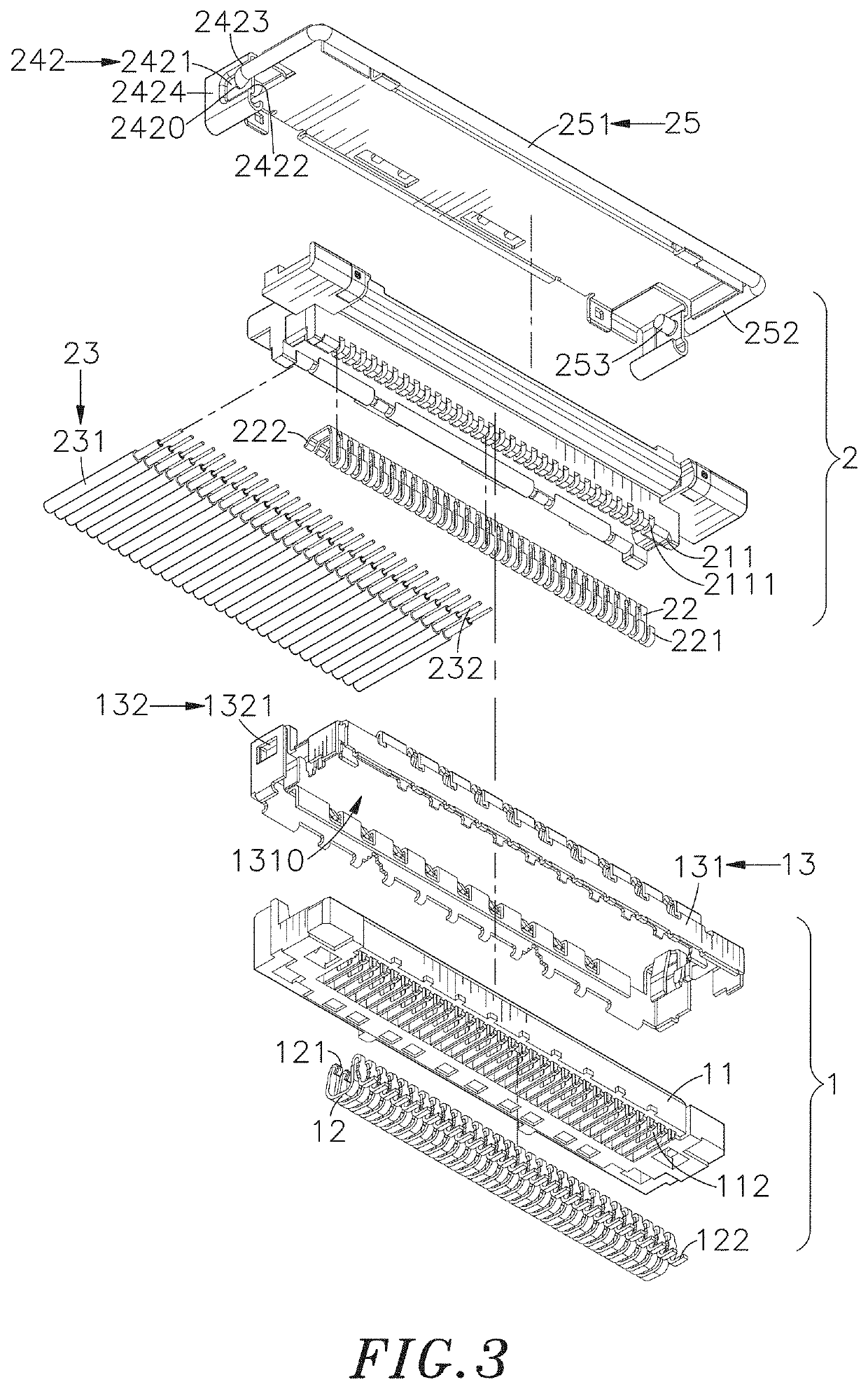
The present invention aims to improve the lock structure of a connector system by adding conductive terminals to a mounting base member and combining it with an outer metal shell, as well as adding contact terminals to a plug connector and combining it with a shielding housing. The invention also includes a handle that can be pulled to rotate, securely locking the connectors together. Additionally, the invention includes guiding surfaces on the pushing parts to ensure smooth rotation of the handle. These improvements increase the simplicity and intuitiveness of the connector system.

Problems solved by technology

The designs of electronic products are tending to be light, thin, short, and small, the sizes of connectors inside various electronic products need to be greatly reduced, and it is more difficult to connect and fasten the thin connectors with general wires or flexible circuits.
However, because the main body and the base are integrally formed by a colloid made of resin, and the manner of mounting the main body and the base by buckling the convex buckle and the buckle groove may cause abrasion due to multiple insertions and connections, and it causes reduction in the overall mounting force of the connector; when the connector is assembled or disassembled, excessive squeeze may also result in damage to the colloid or the structure of the connector.
Furthermore, when the male connector and female connector are connected, conductive terminals and contact terminals are connected through frictional contacts between the single sides thereof, but the fastening effect between these two terminals is not strong enough, and when the male connector and the female connector are impacted or touched by an external force, the male connector may be loosened or separated from the female connector, and it results in unstable signal transmission between the male connector and the female connector.
Therefore, how to solve the above-mentioned problems is a key issue in this industry.

Method used


Image

  • Lock structure of connector assembly
  • Lock structure of connector assembly
  • Lock structure of connector assembly

Examples


Embodiment Construction

[0018]The following embodiments of the present invention are herein described in detail with reference to the accompanying drawings. These drawings show specific examples of the embodiments of the present invention. These embodiments are provided so that this disclosure will be thorough and complete, and will fully convey the scope of the invention to those skilled in the art. It is to be acknowledged that these embodiments are exemplary implementations and are not to be construed as limiting the scope of the present invention in any way. Further modifications to the disclosed embodiments, as well as other embodiments, are also included within the scope of the appended claims. These embodiments are provided so that this disclosure is thorough and complete, and fully conveys the inventive concept to those skilled in the art. Regarding the drawings, the relative proportions and ratios of elements in the drawings may be exaggerated or diminished in size for the sake of clarity and conv...


PUM


Abstract

A lock structure of a connector assembly includes a socket connector and a plug connector. The socket connector includes a mounting base member and conductive terminals disposed in the mounting base member, and the mounting base member is combined with an outer metal shell. A base of the plug connector includes a plug part combined in the docking chamber, and a connection part, and contact terminals. The base is combined with a shielding housing, and a handle is pivoted to shaft holes of the shielding housing. When the plug connector is not locked on the socket connector, the handle is pushed apart from each other, by the shielding housing, and not clasped on the outer metal shell. After the plug connector is combined on the socket connector, the handle can be rotated to return the handle to original locations, and make the handle clasp on the outer metal shell.

Description

BACKGROUND OF THE INVENTION1. Field of the Invention[0001]The present invention provides a lock structure of the connector assembly, and more particularly to a handle pivoted on a plug connector of a lock structure can be pushed apart by a shielding housing when the plug connector is not locked, so as to make the handle not clasp on the outer metal shell of the socket connector; after the plug connector is combined on the socket connector, the handle can be pulled to rotate to elastically return to original locations, to make the handle clasp on the outer metal shell, so as to facilitate to perform lock or unlock operation.2. Description of the Related Art[0002]Generally, connectors are used as connection device and auxiliary accessory for electronic signals and power, and the main function of the connector is to provide connection between various electronic devices or apparatuses, and to ensure that the signals can be accurately transmitted. According to different applied products,...

Claims


Application Information

Patent Timeline
Patent Type & Authority Applications(United States)
IPC IPC(8): H01R13/639H01R13/633H01R13/6581
CPCH01R13/639H01R13/6581H01R13/6335H01R12/79H01R13/6275H01R12/716H01R4/023H01R12/598H01R12/592H01R13/6582
Inventor LIU, YUAN-HUANG
Owner ACES ELECTRONICS CO LTD
Learn More