Supercharge Your Innovation With Domain-Expert AI Agents!

Droplet dispensing device and system

a technology of droplet and dispensing device, which is applied in the field of droplet dispensing device and respective system, can solve the problems of large production effort, unsuitable clinical studies, and significant investment, and achieve the effect of efficient adaptability of the diameter, size and shape of the droplet provided, and efficient connection

Pending Publication Date: 2021-12-30
F HOFFMANN LA ROCHE & CO AG
View PDF10 Cites 0 Cited by
  • Summary
  • Abstract
  • Description
  • Claims
  • Application Information

AI Technical Summary

Benefits of technology

The patent text describes a device that can be used to change the shape of a dome-shaped object, such as a droplet dispensing system. The device can compress or push the dome, causing it to deform, or it can release the dome, allowing its resilient material to return to its original shape. This technology can efficiently achieve the desired results when using the device with a liquid to be dispensed.

Problems solved by technology

However, such devices typically require a significant investment and cause a comparably large effort in production.
Therefore, they are usually not appropriate for clinical studies and the like.
Using such transfer syringes or similar devices, however, typically involves a comparably large number of handling steps which increases the risk of use errors.
Also, it is comparably inconvenient for a person preparing the drug product for administration.

Method used


Image

  • Droplet dispensing device and system
  • Droplet dispensing device and system

Examples


first embodiment

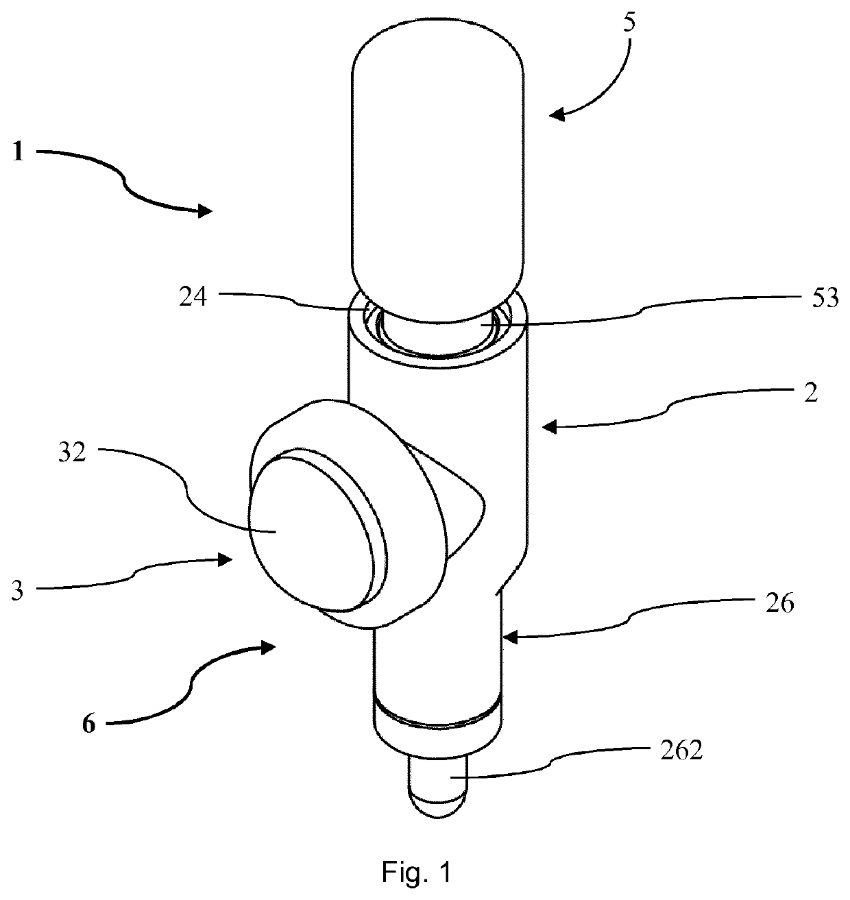
[0039]In FIG. 1 and FIG. 2 a system 1 according to the invention is shown comprising a device 6 according to the invention and a vial 5 with a liquid ophthalmic drug product intended to be administered dropwise into the eye of a patient. The vial 5 is a common bottle-like vial 5 having a hollow interior 51 in which the drug product is arranged, a neck 53 with an opening closed by a cover 52. The cover 52 includes a septum sealing the opening of the neck 53 and a cap holding the septum.

[0040]The device 6 comprises a rigid support body 2 and an elastic spherical dome 3 as dome portion with an actuation portion 32. In other embodiments the dome can also be non-spherical such as for example a flat surface. The body 2 is equipped with a ring shaped mounting flange 28 and the dome 3 with a corresponding mounting notch 31. The dome 3 is put on the body 2 such that the mounting flange 28 is arranged inside the mounting notch 31 thereby forming a tight connection between the dome 3 and the b...

second embodiment

[0048]In FIG. 3 a system 10 according to the invention is shown comprising a device 60 according to the invention and a vial 50 with a liquid ophthalmic drug product intended to be administered dropwise into the eye of a patient. The system 10 is widely embodied identically as the system 1 of FIG. 1 and FIG. 2. In particular, the following features are identical:

[0049]The vial 50 has an interior 510, a neck 530 and a cover 520. The device 60 includes a dome 30 and a support body 20. The body 20 is equipped with a vial seat 240, a nozzle 260 and a transfer conduit 230 between the vial seat 240 and the nozzle 260. The transfer conduit 230 has an end section 2520 ending in a septum of the cover 520 and forming a portion of a spike 250. The nozzle 260 has a socket 2610 and an insert 2620 with a nozzle duct 2630 and a neck section 2640. The dome 30 has an actuation portion 320 and is connected to the body 20 by a mounting flange 280 and a corresponding mounting notch 310 such that a cham...


PUM


Abstract

A device for providing a droplet of a liquid stored in an interior of a vial is disclosed that includes a support body and a resilient dome portion mounted to the support body to form a chamber having air, with the dome portion being configured to create an air flow when activated by compression. The support body includes a vial seat, a nozzle, and air flow and transfer conduits. The support body is arranged, when the vial is received by the vial seat, such that the air flow conduit establishes an air connection between the vial interior and the chamber, the transfer conduit establishes a fluid connection between the vial and the nozzle, and, upon activation of the dome portion, the air flow delivers air into the vial that causes liquid to be transferred from the vial to the nozzle through the transfer conduit.

Description

TECHNICAL FIELD[0001]The present invention relates to a droplet dispensing device and a respective system for providing droplets of liquids. Such devices and systems are, e.g. used in therapeutic or caregiving applications where droplets of medicaments or other liquids are to be administered.BACKGROUND ART[0002]In many therapeutic treatments, pharmaceutical products (below referred to as drug products) are processed and / or administered in droplets, e.g. into body openings or on locations of the body to be treated. For example, in ophthalmologic applications drugs are often administered in droplets directly into the eye. For this purpose, it is known to use devices like pre-filled eye dropper bottles, blow-fill-seal devices or similar specific droplet dispensers.[0003]However, such devices typically require a significant investment and cause a comparably large effort in production. Therefore, they are usually not appropriate for clinical studies and the like. In such applications, if...

Claims


Application Information

Patent Timeline
Patent Type & Authority Applications(United States)
IPC IPC(8): A61F9/00
CPCA61F9/0008G01F11/084B05B11/06
Inventor GAILLOT, MAXIMELEAH, ROBERTAREILLY, DECLANTHUEER, THOMASCARROLL, JACKCOOP, JAMESSIMS, EDWARDTEUCHER, MARK
Owner F HOFFMANN LA ROCHE & CO AG
Features
  • R&D
  • Intellectual Property
  • Life Sciences
  • Materials
  • Tech Scout
  • Unparalleled Data Quality
  • Higher Quality Content
  • 60% Fewer Hallucinations
Learn More