
Methods and apparatus for ultrawide entrance angle reflective articles for use with autonomous vehicle machine vision systems

a machine vision system and ultrawide entrance angle technology, applied in the field of optical elements, can solve the problems of reducing the retroreflectivity of the sheeting, the disadvantage of metallization in reducing the overall retroreflectivity of the article, and the inability to maintain the surface integrity of the sheeting, so as to achieve accurate and safe operation of the vehicle and reduce the effect of optical detection

Active Publication Date: 2021-12-30
VERGENCE AUTOMATION INC
View PDF0 Cites 1 Cited by
  • Summary
  • Abstract
  • Description
  • Claims
  • Application Information

AI Technical Summary

Benefits of technology

The patent describes how to create materials and articles that can reflect light from a wider range of angles, increasing their ability to reflect light and improve visibility. The technology can be used in traffic or roadway signs, making them easier to detect and safely operate vehicles on. The patent also describes an electronic map system that can help drivers navigate through optically blocked roadway elements. Overall, the patent aims to improve the detection and safety of EV safety systems by using ultravide angle reflective technology.

Problems solved by technology

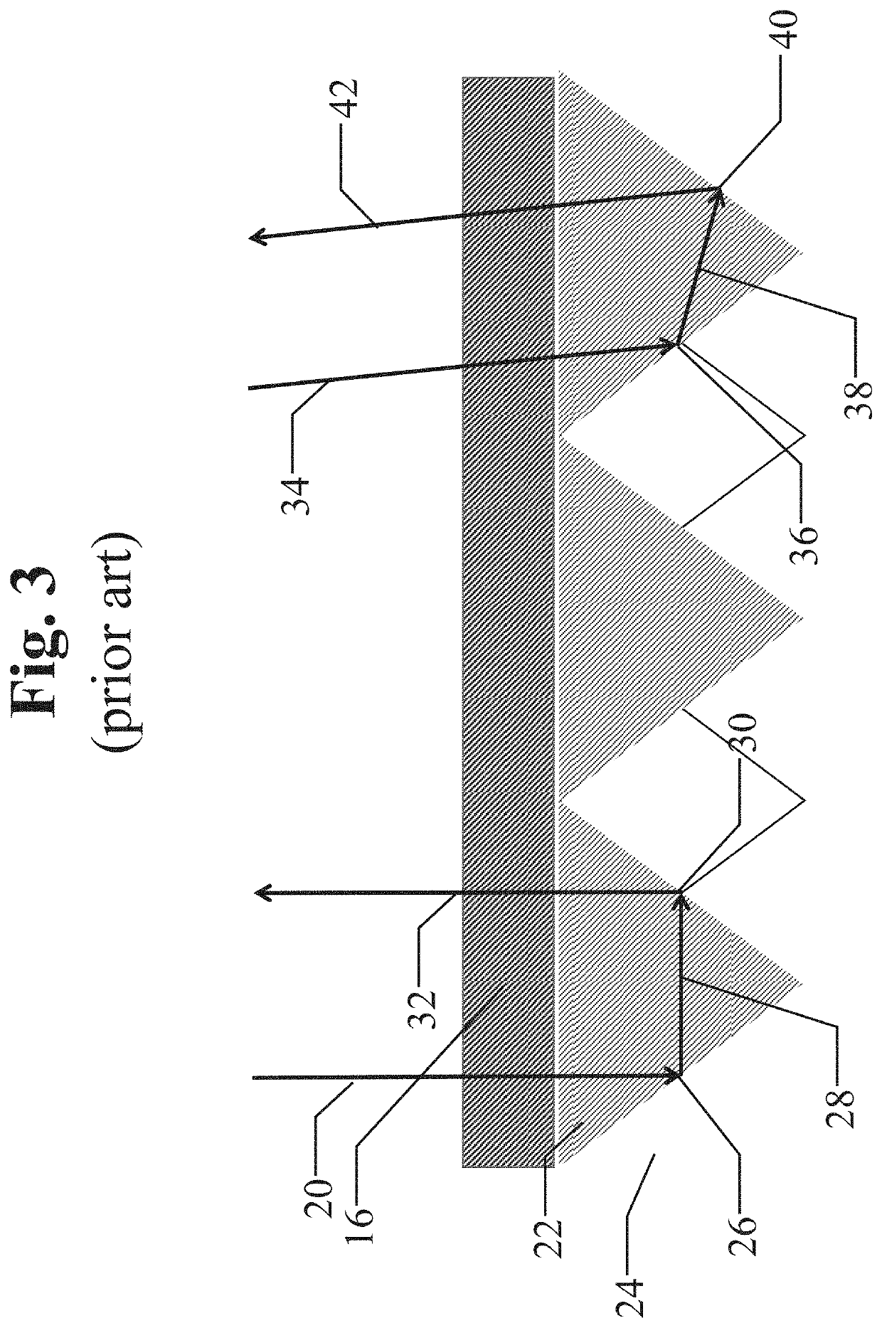
However, even when such an air space is used, light entering the retroreflective elements beyond a certain critical angle will leak out as partially refracted light, thereby reducing the retroreflectivity of the sheeting.
Air spaces behind the reflective base material can also cause problems with durability and with the infusion of foreign, life-reducing materials.
Unfortunately, metallization has the disadvantage of reducing the overall retroreflectance of the article.
Prior art pavement marking materials, and even road signage, can exhibit reduced performance in wet conditions due to varying optical paths for wet and dry conditions.
This construction increases the cost of the article and reduces the durability.

Method used


Image

  • Methods and apparatus for ultrawide entrance angle reflective articles for use with autonomous vehicle machine vision systems
  • Methods and apparatus for ultrawide entrance angle reflective articles for use with autonomous vehicle machine vision systems
  • Methods and apparatus for ultrawide entrance angle reflective articles for use with autonomous vehicle machine vision systems

Examples


Embodiment Construction

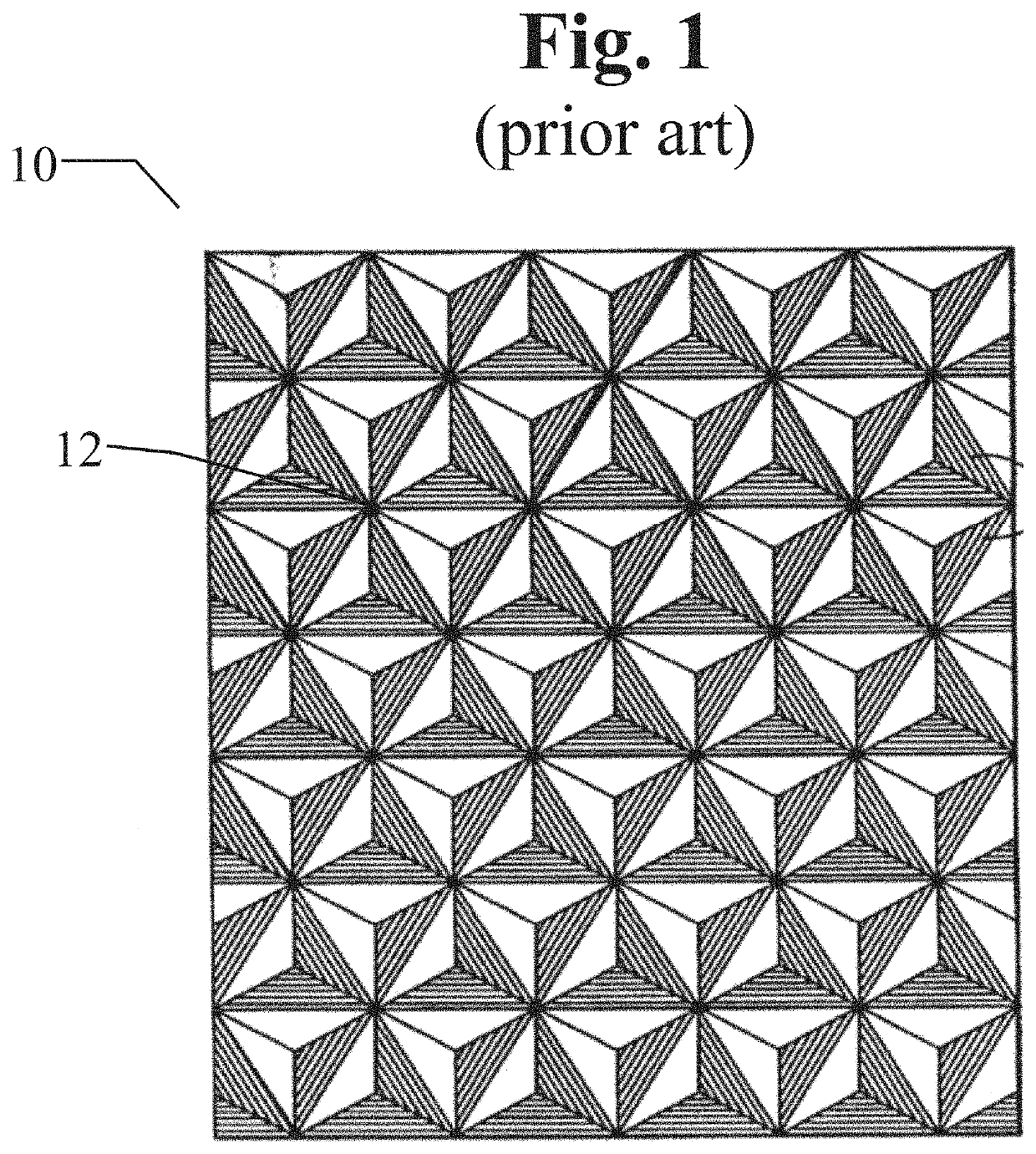
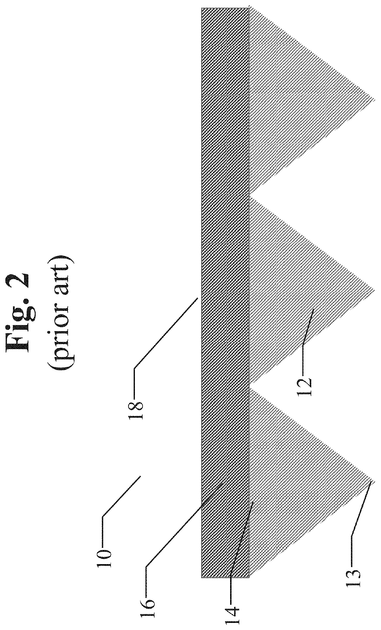
[0053]FIGS. 1 and 2 illustrate a portion of a typical replicated cube corner retroreflective sheet 10 known in the prior art. Referring to both FIGS. 1 and 2, reference 12 generally designates one of the minute cube corner elements of formations prism features disposed in an array on one side of sheeting 10. Each retroreflective element 12 has the shape of a trihedral prism with three exposed planar faces, substantially perpendicular to one another, and an apex axis defined by a line intersecting the apex of the trihedral prism that is equidistant to each of the planar faces. The angle between the faces of the trihedral prism is the same for each cube corner element in the array and will be about 90 degrees.

[0054]As is illustrated in FIG. 2, cube corner elements 12 in sheet 10 can be all of the same dimensions and aligned in an array or pattern of rows and columns, the bases being in the same plane, and adjacent elements being contiguous at the edges of their bases such that there a...


PUM


Abstract

A two-layer retroreflective article construction is enabled that produces higher wide-entrance-angle performance for signs and pavement markings. A single-layer overlay is enabled for existing signs and pavement markers that improve their entrance angle performance. Materials used in the construction of an article or an overlay are transparent to radiation in the range of 400 to 1000 nanometers and utilize TIR (total internal reflection). Minimum performance specifications are proposed that extend sign sheeting retroreflectivity specifications to entrance angles of 60 degrees. An innovative traffic sign design is enabled that increases the positioning performance of safety systems and automated navigation systems.

Description

PRIORITY[0001]This application claims priority to U.S. Provisional Applications Nos. 62 / 718,183 and 62 / 753,207, the contents of which are hereby incorporated by reference.FIELD OF THE INVENTION[0002]The present disclosure relates generally to optical elements that are reflective, such as reflective road markers. More particularly, the present disclosure relates to sign sheeting and pavement marking materials that produce higher levels of net retroreflectivity at larger entrance angles and over a broader electromagnetic spectrum.BACKGROUND OF THE INVENTION[0003]Retroreflective sheeting is often used in roadway signs and conspicuity garments to increase nighttime visibility. Retroreflective adhesive materials are used as pavement markers and vehicle reflectors. Such retroreflective sheeting and materials typically comprise a layer of transparent material having a substantially smooth front surface, and a rear surface provided with a plurality of retroreflective elements. The most comm...

Claims


Application Information

Patent Timeline
Patent Type & Authority Applications(United States)
IPC IPC(8): E01F9/512G02B5/124G06K9/00
CPCE01F9/512G02B2027/0138G06K9/00818G02B5/124E01F9/619G06V20/582G02B2027/014G02B2027/0141G02B27/0101
Inventor RETTERATH, JAMES E.
Owner VERGENCE AUTOMATION INC
Learn More