
Retroreflective sheet

a technology of retroreflective sheets and dents, applied in the field of retroreflective sheets, can solve the problems of reducing the retroreflectivity of the sheet, so as to achieve a less likely deterioration of the retroreflectivity

Active Publication Date: 2020-10-01
NIPPON CARBIDE KOGYO KK
View PDF0 Cites 0 Cited by
  • Summary
  • Abstract
  • Description
  • Claims
  • Application Information

AI Technical Summary

Benefits of technology

The technical effect of this patent text is to provide a retroreflective sheet that is less likely to have its retroreflectivity compromised when it is used for a printed object that is bent or embossed.

Problems solved by technology

However, in the retroreflective sheet disclosed in Patent Literature 1 described above, the voids formed between the retroreflective elements and the dents might be crushed due to application of pressure in a thickness direction as a result of bending or embossing.
Therefore, the retroreflective sheet disclosed in Patent Literature 1 described above might have the retroreflectivity compromised when it is used for a printed object bent or embossed, compared with a case where it is used for a flat object.

Method used


Image

  • Retroreflective sheet
  • Retroreflective sheet

Examples


Embodiment Construction

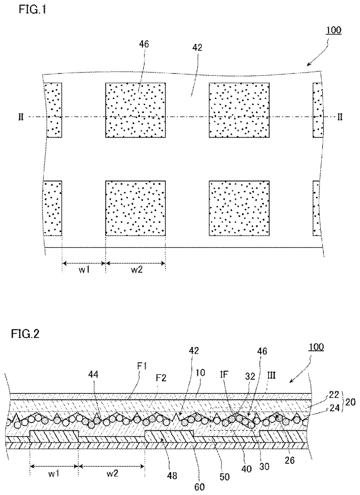
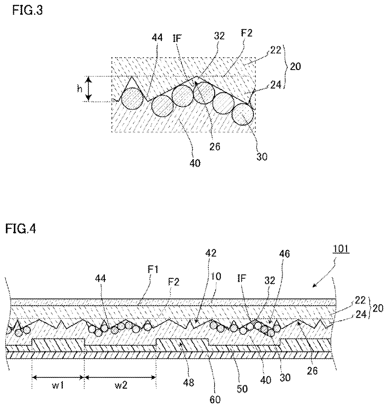
[0038]Hereinafter, a preferred embodiment of a retroreflective sheet according to the present invention will be described in detail with reference to the drawings.

[0039]FIG. 1 is a schematic plan view illustrating a retroreflective sheet according to an embodiment. FIG. 2 is a schematic cross sectional view of the retroreflective sheet illustrated in FIG. 1 in a thickness direction, taken along line II-II. In each of FIGS. 1 and 2 and other drawings referred to in the following description, the size of each component is illustrated in an exaggerated manner or the like, and thus is not accurately illustrated for the sake of easy understanding. Furthermore, in each of FIGS. 1 and 2 and other drawings referred to in the following description, the same reference numerals are given to components having the same configuration, and repeated reference numerals are omitted.

[0040]As illustrated in FIG. 2, the retroreflective sheet 100 according to the present embodiment includes a surface pro...


PUM


Abstract

A retroreflective sheet includes: a retroreflective layer (20) including a plurality of retroreflective elements (24) on one surface; a back face layer (40) provided to face the surface of the retroreflective layer (20) on the side of the retroreflective elements (24) and including a bonding portion (42) bonded to the retroreflective elements (24); and a plurality of particles (30) disposed between the retroreflective elements (24) and the back face layer (40). The bonding portion (42) is continuously formed to surround a plurality of capsule portions (46) in plan view. Voids (32) are formed between the retroreflective elements (24) and the back face layer (40) in the plurality of capsule portions (46).

Description

TECHNICAL FIELD[0001]The present invention relates to a retroreflective sheet.BACKGROUND ART[0002]The retroreflective sheet has a property of allowing light incident thereon to be reflected toward a light source. Due to such a property, the retroreflective sheet is used for a purpose such as raising visibility of a target object (such as a printed object) irradiated with light during nighttime or in a dark place. The retroreflective sheet is used for, for example, traffic signs, guide signs, vehicle license plates, advertisement signs, traffic lane separators, delineators, and the like.[0003]An example of such a retro reflective sheet is disclosed in Patent Literature 1 described below. The retroreflective sheet includes: a light transmissive layer including retroreflective elements; and a resin back face layer provided with multiple dents smaller than the retroreflective elements, on a surface facing a surface of the light transmissive layer on which the retroreflective elements ar...

Claims


Application Information

Patent Timeline
Patent Type & Authority Applications(United States)
IPC IPC(8): G02B5/124G02B1/14
CPCG02B5/124G02B1/14B32B7/02B32B37/10
Inventor SHIOMI, TOSHIAKIJIANG, CHENYANG
Owner NIPPON CARBIDE KOGYO KK
Learn More