
Dispenser for dispensing a fluid

a technology for dispensing fluids and dispensers, which is applied in the direction of spraying apparatuses, single-unit apparatuses, etc., can solve the problems of long sorting time, inefficient recycling of two components, and user who is not very careful,

Active Publication Date: 2022-01-06
APTAR ITAL
View PDF0 Cites 0 Cited by
  • Summary
  • Abstract
  • Description
  • Claims
  • Application Information

AI Technical Summary

Benefits of technology

The invention is a dispenser for fluid that has the following technical effects: a simple structure for use in systems that require compensation systems, a degree of robustness that allows it to be dispatched without special protective devices, and features for safe recycling. The dispenser includes a ring that is coupled to the deformable element in a way that creates an outlet valve and allows the deformable element to align or misalign with the partial grooves of the ring to open or close a passage for compensating the reduction in the volume of liquid in the bottle as it is gradually emptied.

Problems solved by technology

Disadvantageously, these devices are made of materials different from those of the bottles to which they are coupled and a user who is not very careful might not separate the dispenser from the bottle when disposing of the waste.
In this way the recycling of the two components is not efficient and, especially when arriving in an area for sorting the waste, requires lengthy sorting times.
Moreover, from a functional point of view of the dispensers, a further drawback is linked to the simplified nature of the structure of the dispensers.
Disadvantageously, these elements do not have compensating systems and are not therefore able to top-up the volume of product extracted from the bottle as they are generally used for systems which do not require it.
Moreover, prior art dispensers require certain construction specifications in order to allow the transport in safety, which is a feature disadvantageously missing in the above-mentioned simplified structures.

Method used


Image

  • Dispenser for dispensing a fluid
  • Dispenser for dispensing a fluid
  • Dispenser for dispensing a fluid

Examples


Embodiment Construction

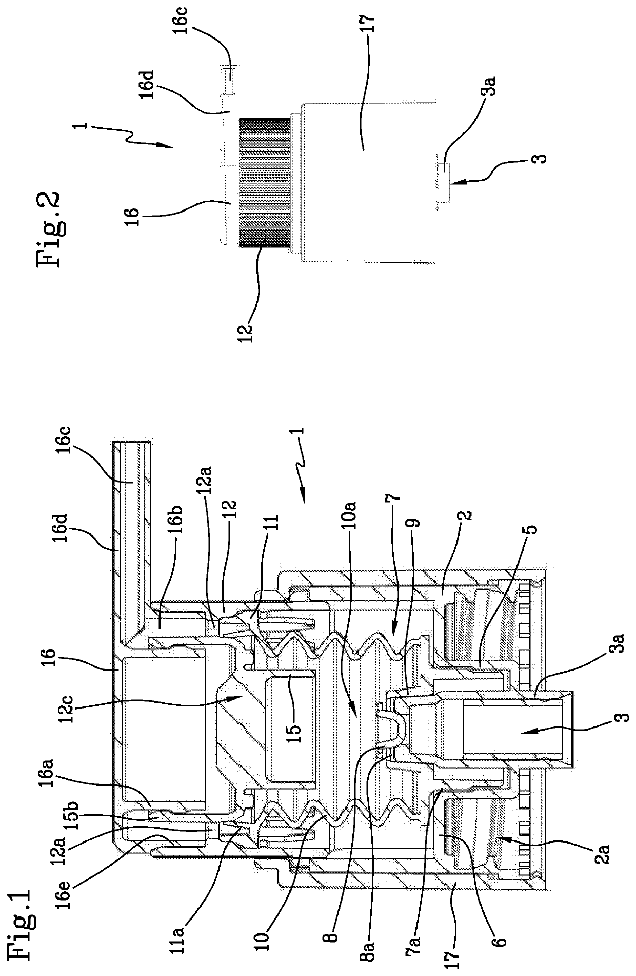
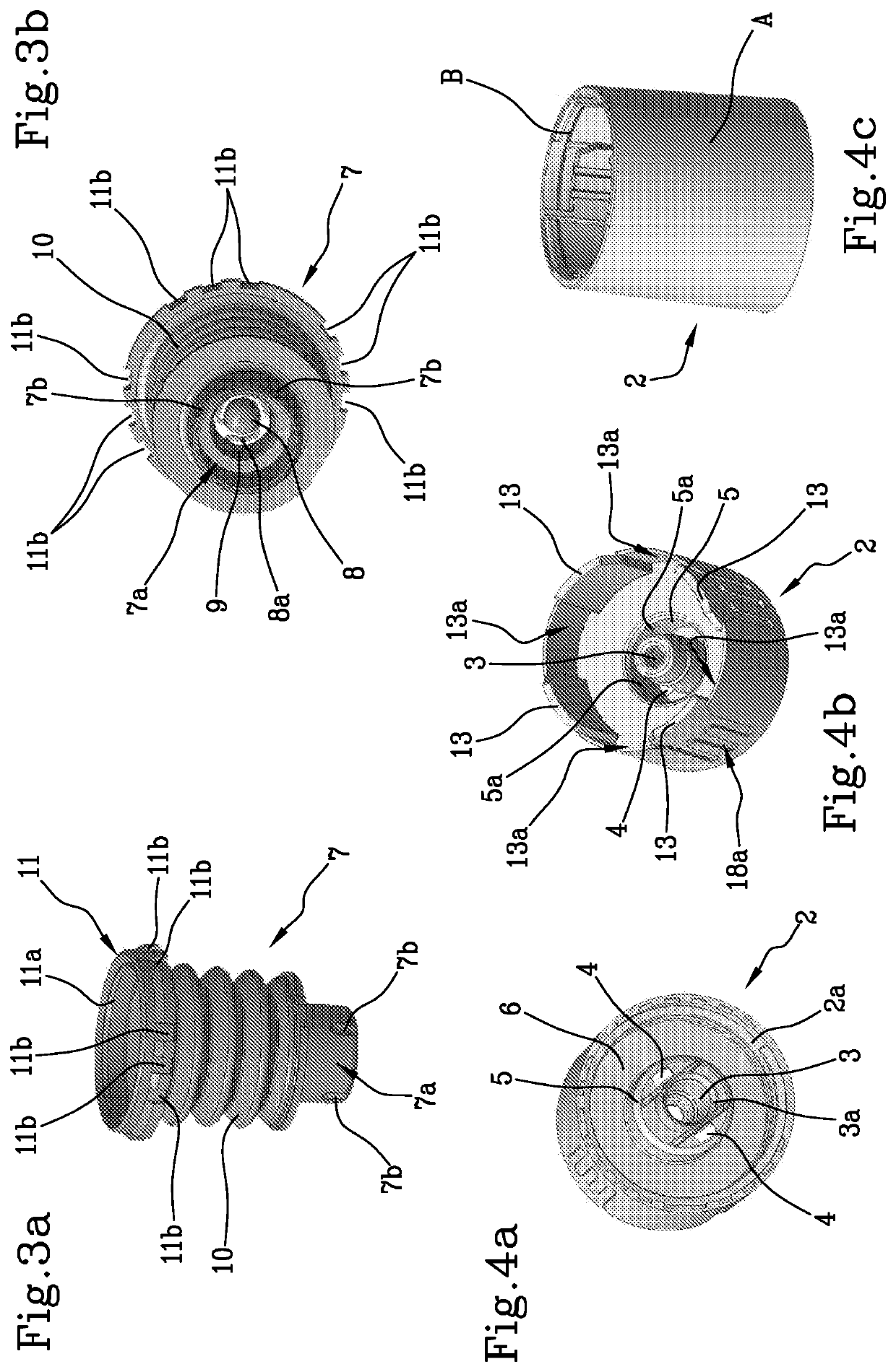
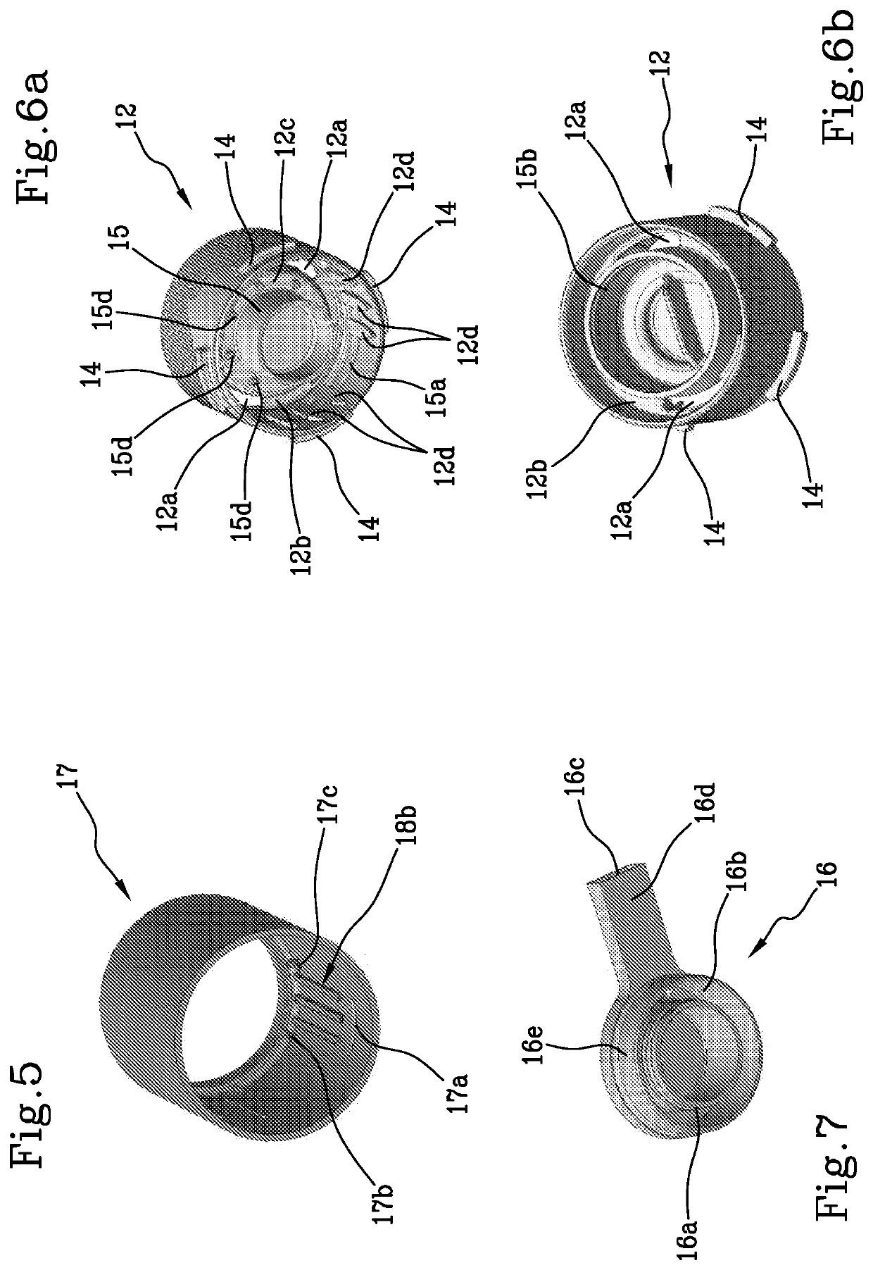
[0028]With reference to the accompanying drawings, the numeral 1 denotes in its entirety a dispenser for dispensing a fluid which, for simplicity of description, will be referred to hereafter as the dispenser 1.

[0029]The dispenser 1 is made of plastic material in such a way as to simplify the recycling. Preferably, the dispenser 1 is made of polyethylene. Even more preferably, the plastic material is a biological plastic produced from non-fossil sources. In other words, the components from which the dispenser 1 is made are sized in such a way as to be made from a single plastic family (for example, polyethylene) so that it can also be recycled together with bottles which, when not transparent, are also made of polyethylene. Advantageously, in the polyethylene family there are the above-mentioned biological plastics (made from non-fossil sources) which are particularly recyclable and / or biodegradable.

[0030]The dispenser 1 comprises a ring nut 2 which can be screwed onto the neck of a...


PUM


Abstract

Described is a dispenser for dispensing a fluid, made of plastic material, including: —a ring nut having an inner cylindrical wall equipped with partial grooves; —a concertina-like deformable element, defining a return spring of the dispenser and including a cylindrical lower projection equipped with relative partial grooves; —a ring designed to define with the ring nut a locking system designed to define an operating configuration and a non-operating configuration of the dispenser in such a way as to pull the concertina-like deformable element in such a way as to align the partial grooves of the cylindrical wall of the ring nut and the partial grooves of the concertina-like deformable element.

Description

CROSS-REFERENCE TO RELATED APPLICATIONS[0001]This application is the U.S. national phase of International Application No. PCT / IB2019 / 059165 filed Oct. 25, 2019 which designated the U.S. and claims priority to IT 102018000020692 filed Dec. 21, 2018, the entire contents of each of which are hereby incorporated by reference.BACKGROUND OF THE INVENTIONField of the Invention[0002]This invention relates to a dispenser for dispensing a fluid. In other words, the invention relates to a dispensing device applicable to the neck of a bottle in order to dispense the fluid contained in the bottle.Description of the Related Art[0003]There are various types of prior art dispensers, from those which are structurally complex to those which are structurally simpler.[0004]Generally speaking, the use of dispensers is known which are equipped with a simple structure and therefore with a reduced number of components so as to have environmentally-sustainable products equipped with homogeneous material in ...

Claims


Application Information

Patent Timeline
IPC IPC(8): B05B11/00
CPCB05B11/3033B05B11/0044B05B11/3047B05B11/3059B05B11/0089B05B11/3035B05B11/1033B05B11/1035B05B11/1047B05B11/1059
Inventor CARTA, LAMBERTO
Owner APTAR ITAL
Learn More