Head of a tag device

a tag device and head technology, applied in the field of tags, can solve the problems of increasing the cost of attaching labels, and difficult to control the vacuum pressure or positive pressure of the vacuum holes, and achieve good stability of the tag

Active Publication Date: 2022-01-06
POWERTECH TECHNOLOGY
View PDF2 Cites 1 Cited by
  • Summary
  • Abstract
  • Description
  • Claims
  • Application Information

AI Technical Summary

Benefits of technology

[0009]Based on the foregoing description, the negative-pressure through holes and the positive-pressure through holes are distributed between the two short sides of the body, so a suction area of the head is expanded to cover the entire second surface. Therefore, the label is sucked by the selected negative-pressure through holes on a specific position of the second surface of the head according to the position of the components to be attached. Furthermore, a positive-pressure airflow is provided by the selected positive-pressure through holes corresponding to the position of the components to be attached. The present invention does not require different customized heads of the tag device for different products, provides a good stability tag task and increases UPH.
[0015]Based on the foregoing description, in the controlling method the negative-pressure air tube and positive-pressure air tube are respectively inserted into the corresponding first and second connectors according to the positions of the component on the product. Then the label is successfully and tightly attached on the component. Therefore, the label suction area of the head is adjustable to align the component on the product. The present invention provides a good stability tag task for the components with different positions and increases UPH.

Problems solved by technology

Therefore, more different products need more different heads and time and cost of attaching labels are increased accordingly.
If the components on the product have different positions and / or different heights, it is hard to control the vacuum pressure or positive-pressure of the vacuum holes 81 and the stability of attaching labels is not good enough.
Therefore, the bad stability causes that a failure rate of the tag device is increased, a rework rate is increased and productivity (unit per hour; UPH) is decreased.

Method used


Image

  • Head of a tag device
  • Head of a tag device
  • Head of a tag device

Examples


Embodiment Construction

[0028]The present invention provides a head of a tag device for different products. With an embodiment and drawings thereof, the features of the present invention are described in detail as follow.

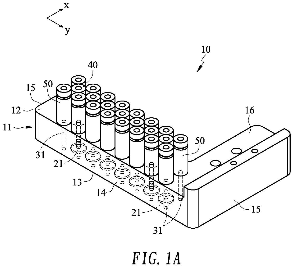
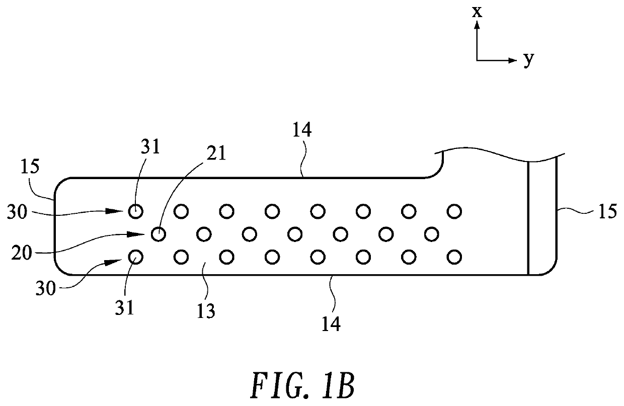
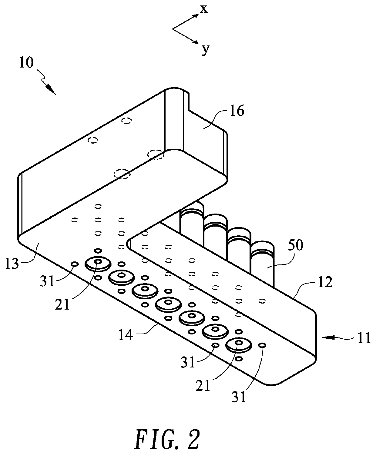
[0029]With reference to FIGS. 1A, 1B and 2, the head 10 of the tag device of the present invention has a body 11, at least one row of negative-pressure through holes 20 and at least one row of positive-pressure through holes 30.

[0030]The body 11 has a first surface12, a second surface 13, two opposite long sides 14 and two opposite short sides 15. In one embodiment, the body 11 further has a connecting part 16 vertically extended from one of the short sides 15 and the connecting part 16 is used to connect the tag device (not shown).

[0031]The at least one row of negative-pressure through holes 20 has a plurality of negative-pressure through holes 21 formed through the first and second surfaces 11, 12 of the body 11 and arranged equidistantly according to a long-axis direction Y of the body ...


PUM

PropertyMeasurementUnit
pressureaaaaaaaaaa
positive-pressureaaaaaaaaaa
lengthaaaaaaaaaa

Abstract

A head of a tag device having a body, at least one row of negative-pressure through holes and at least one row of positive-pressure through holes. The body has a first surface and a second surface. The rows of negative and positive-pressure through holes are formed through the first and second surfaces of the body and arranged along a long-axis direction. Two negative and positive-pressure through holes at both ends of the corresponding row of negative and positive-pressure through holes are respectively close to the short sides of the body. Therefore, an effective labeling area is distributed between two short sides. The head of the tag device of the present invention provides a stable labeling operation for different products where different components are mounted and increases units per hour (UPH).

Description

BACKGROUND OF THE INVENTION1. Field of the Invention[0001]The present invention is related to a tag device, and more particularly to a head of a tag device.2. Description of the Prior Arts[0002]After different products are manufactured, different tags are required to paste on corresponding products respectively. Since the different products have different components mounted thereon, different heads of a tag device are required to attach a label to corresponding product successfully.[0003]With reference to FIG. 7A, a head 80 of the tag device is illustrated. The head 80 has a plurality of vacuum holes 81 and the vacuum holes 81 are formed on a middle area of an attaching surface 801 of the head 80. The head 80 is moved to a top of a product and the vacuum holes 81 thereon are placed on a top of at least one component on a middle area of the product. A label is successfully attached to the at least one component. With further reference to FIG. 7B, another head 80′ of the tag device is...

Claims


Application Information

Patent Timeline
Patent Type & Authority Applications(United States)
IPC IPC(8): B65C9/28B65C7/00
CPCB65C9/28B65C7/00B65C9/14B32B11/00
Inventor YANG, CHING-CHIACHEN, SHIN-KUNGLU, YUAN-JUNGCHEN, YEN-YUPENG, HSING-FULIN, PAO-CHEN
Owner POWERTECH TECHNOLOGY
Why Eureka
Try Eureka