
Vacuum assisted sealing processes and systems for increasing air cavity package manufacturing rates

a vacuum assisted sealing and air cavity technology, applied in the direction of electrical equipment, basic electric elements, semiconductor/solid-state device details, etc., can solve the problems of increasing the gas pressure in the package, reducing and reducing the leak-free seal effect, so as to reduce the internal pressure of the package and increase the uph of the electronic packag

Inactive Publication Date: 2018-10-30
RJR TECH INC
View PDF16 Cites 0 Cited by
  • Summary
  • Abstract
  • Description
  • Claims
  • Application Information

AI Technical Summary

Benefits of technology

This patent describes a method for assembling electronic packages more quickly and with better quality. The method involves creating a vacuum inside the package components to decrease internal pressure before sealing them, which speeds the sealing process and reduces the likelihood of blowouts or pin holes. The method also allows for multiple packages to be assembled simultaneously and processed more accurately. In addition, the method includes an internal compression stop to ensure consistent heights of the mated package assembly, regardless of variations in components specifications or bond line thicknesses.

Problems solved by technology

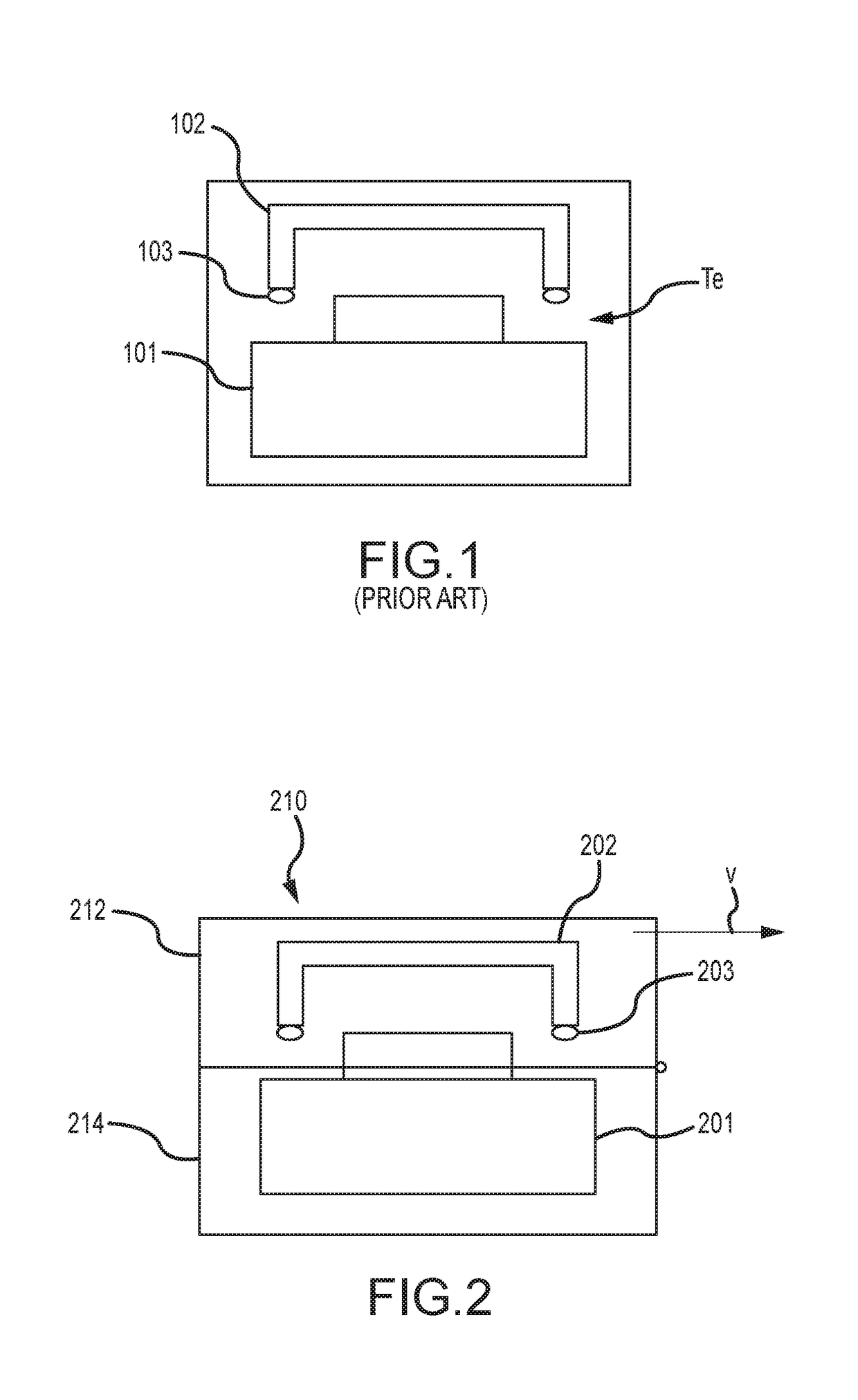
However, using such procedures often resulted in undesirable anomalies such as “pin holes” or “blowouts.” Specifically, when the adhesive between clamped pieces is heated from room temperature to its curing temperature, the adhesive becomes soft and sticky and the clamping force causes it to flow and make a leak-free seal.
The result of continued heating causes the gas pressure in the package to rise, and because the higher temperature also causes the adhesive to become thinner (i.e., have a lower viscosity), its ability to hold the gas is diminished, forcing gas through the seal and creating blowouts or pin holes.
However, if the adhesive has hardened too much, it may not be able to reflow over the blowout, leaving a pin hole or blowout.
While a positive pressure may remain after the lid makes contact with the body by virtue of the closing of the cavity, the remaining pressure generally will not be sufficient to cause pin holes or blowouts.
However, while such preheating is an effective solution for preventing blowouts, it has some disadvantages as well.
Additionally, using existing manufacturing processes, obtaining a sealed package that has consistent alignment and height each time can be challenging.

Method used


Image

  • Vacuum assisted sealing processes and systems for increasing air cavity package manufacturing rates
  • Vacuum assisted sealing processes and systems for increasing air cavity package manufacturing rates
  • Vacuum assisted sealing processes and systems for increasing air cavity package manufacturing rates

Examples


Embodiment Construction

[0030]Persons skilled in the art will readily appreciate that various aspects of the present disclosure can be realized by any number of processes, systems, structures, and components configured to perform various functions disclosed herein. Stated differently, other such processes, systems, structures, and components can be incorporated herein to perform the intended functions. It should also be noted that the accompanying drawing figures referred to herein are not all necessarily drawn to scale, and may be exaggerated to illustrate various aspects of the present disclosure, and in that regard, the drawing figures should not be construed as limiting.

[0031]Additionally, the present disclosure contemplates the manufacture of various electronic packages now known or as yet unknown in the art. While at various times specific embodiments of electronic packages and the components that such packages are manufactured from are referred to herein, it should be appreciated that this disclosur...


PUM


Abstract

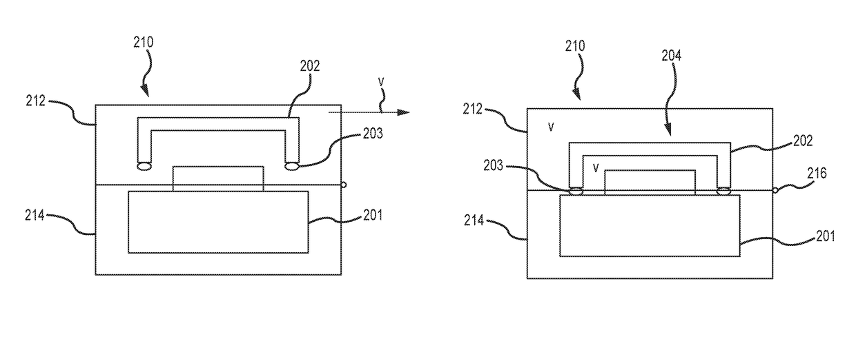
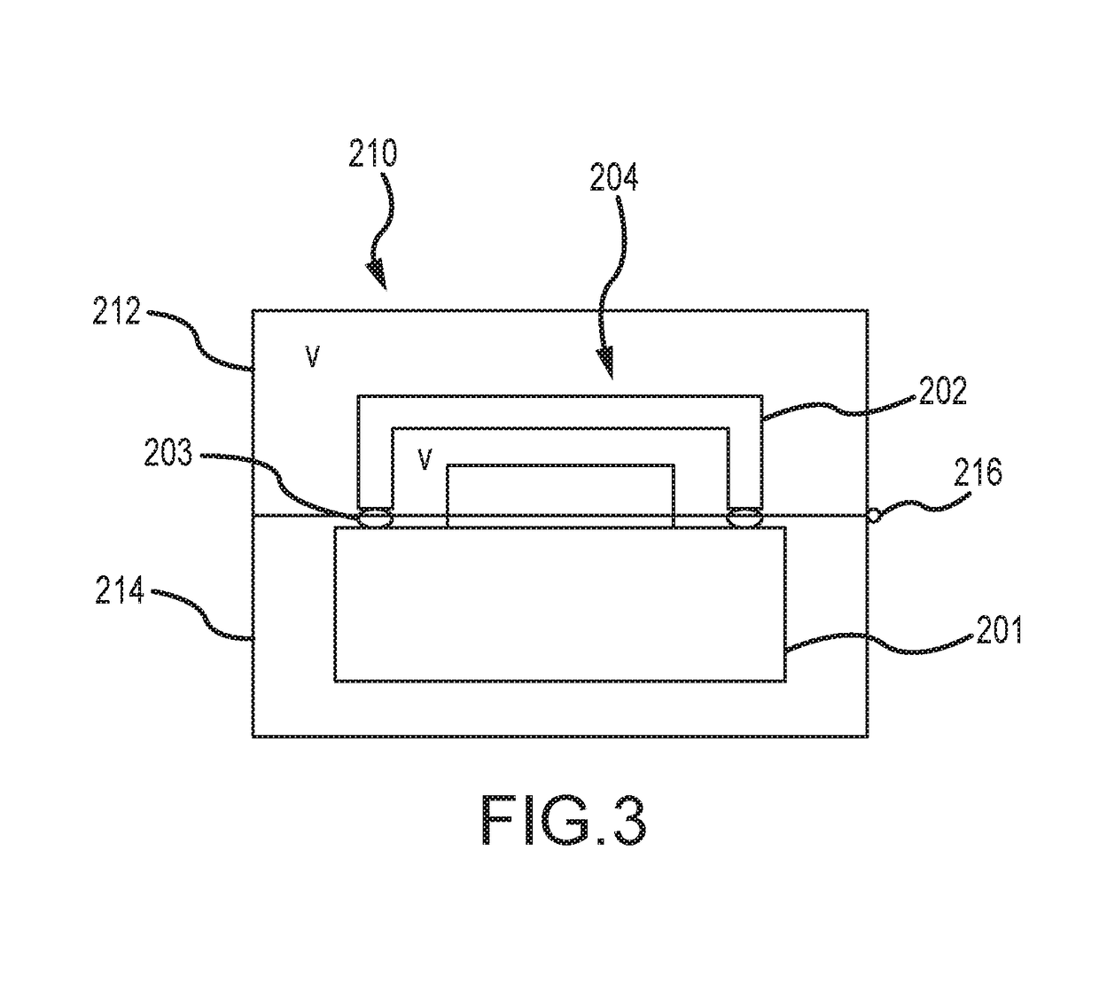
The present disclosure describes a sealing processes and structure for sealing air cavity electronic packages using a thermosetting, thermal plastic, other known or as yet unknown adhesives, or hybrid combinations of such adhesive(s). Processes disclosed comprise steps of providing a base and a lid, with at least one of the base and the lid having a mating surface coated with the adhesive. Initially, an air gap is maintained between the base, the lid, and the adhesive and a vacuum is generated around the base, the lid, and the adhesive. Once the vacuum has been generated, the base and the lid are mated to create a mated package assembly with a vacuum therein. After the mating, the mated package assembly is heated to a curing temperature to cure the adhesive, and pressure may be applied as well. Because the air within the mated package assembly has been evacuated prior to heating, there is no air pressure build-up therein, reducing or eliminating the presence of blowouts and pin holes.

Description

FIELD[0001]The present disclosure relates generally to sealing processes and sealing apparatus that use adhesives to seal electronic packages, devices, containers and the like that, after sealing, have a cavity within. The present disclosure also relates generally to locating mechanisms to maintain consistent part alignment and height of the sealed components.BACKGROUND[0002]Conventional methods for sealing electronic packages having a cavity therein (or “air cavity packages”) use adhesives to attach a package header (typically, a two piece package made from ceramic ring attached to a base with leads attached, or other similar materials and designs) and / or a package base / body combination (typically, a three piece air cavity plastic package that uses a base, a body or sidewall, and a lid) and a package lid mated together in known fixtures, sealing systems, “clip and bake” systems, or systems and processes for mating and sealing the components. In this regard, an organic adhesive is t...

Claims


Application Information

Patent Timeline
Patent Type & Authority Patents(United States)
IPC IPC(8): H01L21/52H01L21/50
CPCH01L21/50H01L21/52H01L21/67126H01L21/563H01L21/565H01L21/67098H01L21/67121H01L21/67144H01L21/67248H01L21/67259H01L23/28
Inventor ROSS, RICHARD J.NI, JOHNBREGANTE, RAYMOND J.FU, BIAOBREGANTE, MICHAELAMPARO, CRESENCIO
Owner RJR TECH INC
Learn More