
Method and system to implement wideband retro-reflective wave mechanics

a wave mechanics and wideband technology, applied in the field of wideband retroreflective wave mechanics, can solve the problems of narrowing the effective size or width of wave mechanics, and increasing the cost of two or more independent systems, so as to achieve higher transmitter power levels and higher received power

Inactive Publication Date: 2022-01-06
JUDD MANO
View PDF4 Cites 0 Cited by
  • Summary
  • Abstract
  • Description
  • Claims
  • Application Information

AI Technical Summary

Benefits of technology

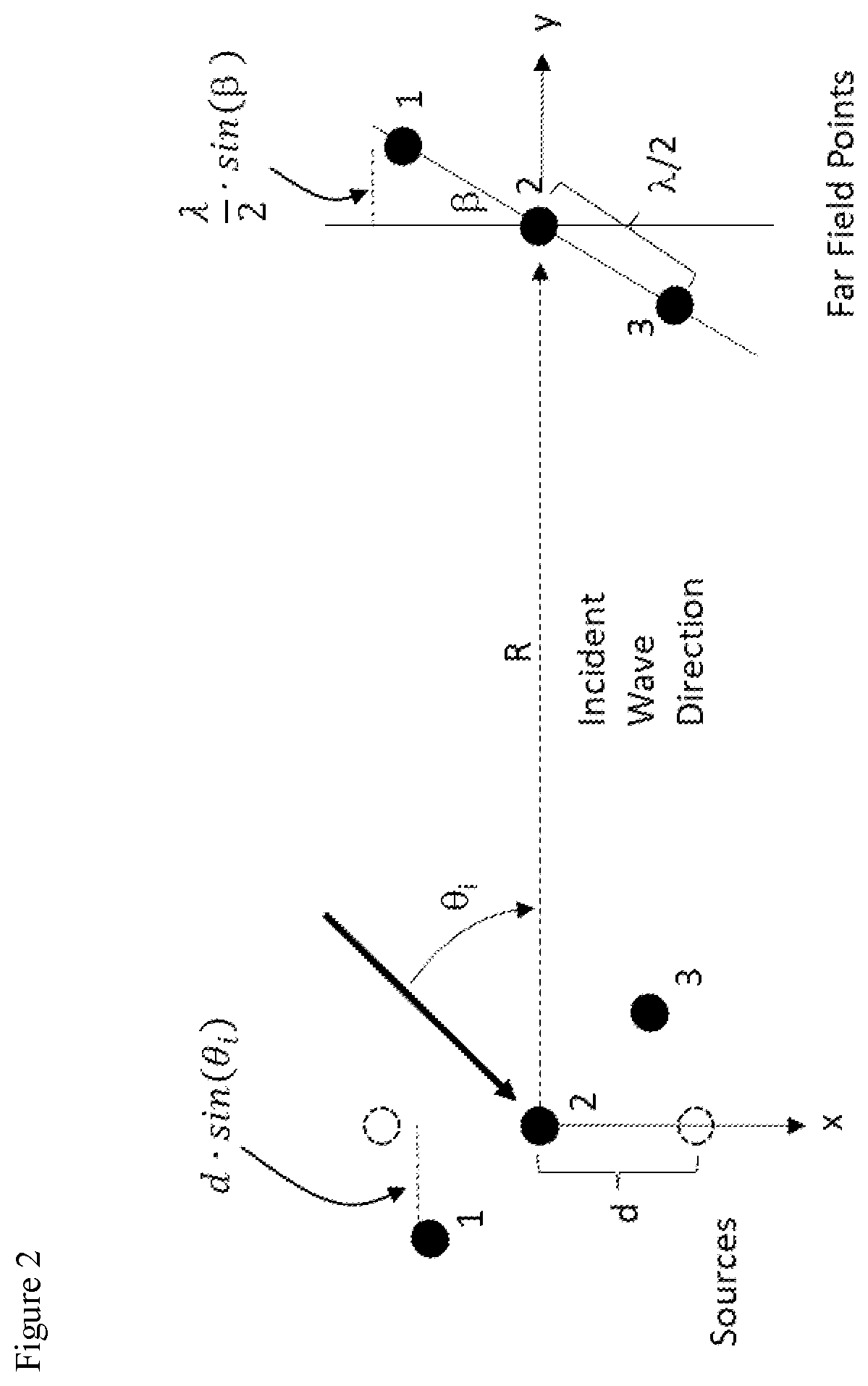
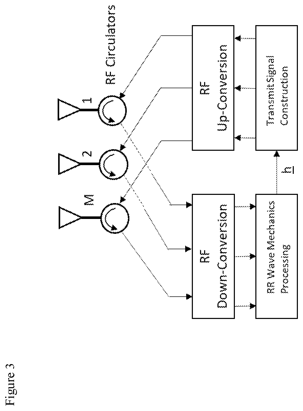
The invention combines Wave Mechanics and Retro-Reflection to process far field emitted signals using multiple antennas. By breaking up the signal into different frequency ranges and solving for the weight vector of each range, the method creates a pre-determined wavefront rotation and higher received power compared to other methods. This overcomes the limitations of Wave Mechanics and allows for better control of the signal's rotation.

Problems solved by technology

The primary issue with co-location of all antennas within a small area is that the effective size or width of the wave mechanics resultant (width of the expanding wave front in the far field) becomes narrower as the desired rotation angle is increased and as range is increased.
However, the cost is in the requirement of two or more independent systems, that are also coherently synchronized.
The problem is how to accurately and cost effectively project the Wave Mechanics phenomenon at great range, but also to such a small width.

Method used


Image

  • Method and system to implement wideband retro-reflective wave mechanics
  • Method and system to implement wideband retro-reflective wave mechanics
  • Method and system to implement wideband retro-reflective wave mechanics

Examples


Embodiment Construction

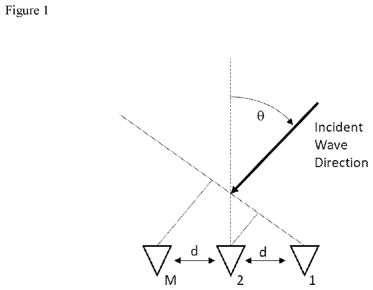
[0016]First, we review the Narrowband Retro-Reflective Wave Mechanics technique:

[0017]FIG. 1 shows M antennas in a linear array, spaced by d. Assume M antennas. The mth component (m=1, 2, . . . , M) of the steering vector can be represented as:

am=Gm(θ)exp−j·(m-1)·k·d·sin(θi)

[0018]Where:

[0019]Gm(θ)=the antenna voltage of the mth antenna, in the θ direction

[0020]K=wave number=2π / λ

[0021]d=sensor to sensor spacing, assumed equal in this model.

[0022]θi=Incident signal direction of arrival, to the line normal to the array.

[0023]This mth component of the steering vector can also be represented as a function of frequency or simply an electrical phase:

am=Gm⁡(θθi)⁢exp-j·(m-1)·(ω⁢ / ⁢c)·d·sin⁡(θi)=Gm⁡(θi)⁢exp-j·ϕm

[0024]Where:

[0025]ω=radial frequency, and

[0026]c=speed of light, and

[0027]ϕm=phase of the mth antenna, relative to a common reference phase

[0028]For this simplistic model, the sensor to sensor spacing(s) are equal.

[0029]Assume also, for this simplified model, that the antenna gains are...


PUM


Abstract

Methodology to combine Wave Mechanics with Retro-Reflection, to take in the Far Field emitted (incident) Wideband signal via a small array, process the signal and Retro-Reflectively re-transmits the Wideband signal back out, with the Wave Mechanics rotation mechanism injected into the array weights.

Description

[0001]The present application claims priority to the earlier filed provisional application having Ser. No. 62 / 872,580, and hereby incorporates subject matter of the provisional application in its entirety.BACKGROUND[0002]Retro-Reflection is defined as a process in which an incident signal is reflected back to the point of origin. In the Radio Frequency (RF) community, Retro-Reflective systems capture the incident RF signal energy and blindly re-transmit this signal. Radar Cross-Eye is one example of a Retro-Reflective System. The term blindly means that no source location or bearing angle information is required. Thus eliminating the need for a complex or expensive passive Direction Finding (DF) system to obtain the incident signal Angle of Arrival (AOA) or Direction of Arrival, and to compute a set of weights that would be used to transmit a copy of the signal back towards the incident signal direction (path). For most Retro-Reflection systems, the output weight vector or steering ...

Claims


Application Information

Patent Timeline
IPC IPC(8): G01S13/06G01S15/06
CPCG01S13/06G01S15/06G01S2013/0245G01S13/42G01S15/42
Inventor JUDD, MANO
Owner JUDD MANO
Learn More