
Inertial cooktop and manufacturing method

a technology of a cooktop and a manufacturing method, applied in the direction of roasters/grills, cooking-vessel materials, kitchen equipment, etc., can solve the problems of product loss of ease of maintenance and food-related functions, non-planar surface, and fragile material deterioration, and achieve a high level of resistance

Pending Publication Date: 2022-01-13
SISTERIA
View PDF8 Cites 0 Cited by
  • Summary
  • Abstract
  • Description
  • Claims
  • Application Information

AI Technical Summary

Benefits of technology

The present invention proposes a new griddle device that can solve problems of low resistance on the cooking surface. The new device has high thermal inertia, meaning it can withstand high temperatures and has a slow reaction time. This makes it easier to control the temperature and prevents the cooking surface from getting too hot or too low. The technical effects of the new device are improved cooking performance and safety.

Problems solved by technology

The latter nevertheless remains fragile.
Indeed, the facing may flake over time, making the product lose the ease of maintenance and the food-related function thereof.
Regarding the cast iron itself, this tends to deform over time, thus forming a non-planar surface impeding cooking (with areas retaining fat, in particular).
This facing has a very resistant cooking surface and offers very easy maintenance, but has, on the other hand, poor thermal homogeneity.
Stainless steel is, indeed, a bad conductor of heat, and such a cooktop then requires a large number of burners to compensate for this phenomenon.
The energy consumption is then clearly increased.
By contrast, the main defect thereof is that it rusts over time and therefore requires regular maintenance to counter this phenomenon.
Similarly, the inertia and the heat conduction of this material remain clearly inferior than those of cast iron.
As is seen, each of these devices has various specific problems that hinder the widespread use of griddles.

Method used


Image

  • Inertial cooktop and manufacturing method

Examples


Embodiment Construction

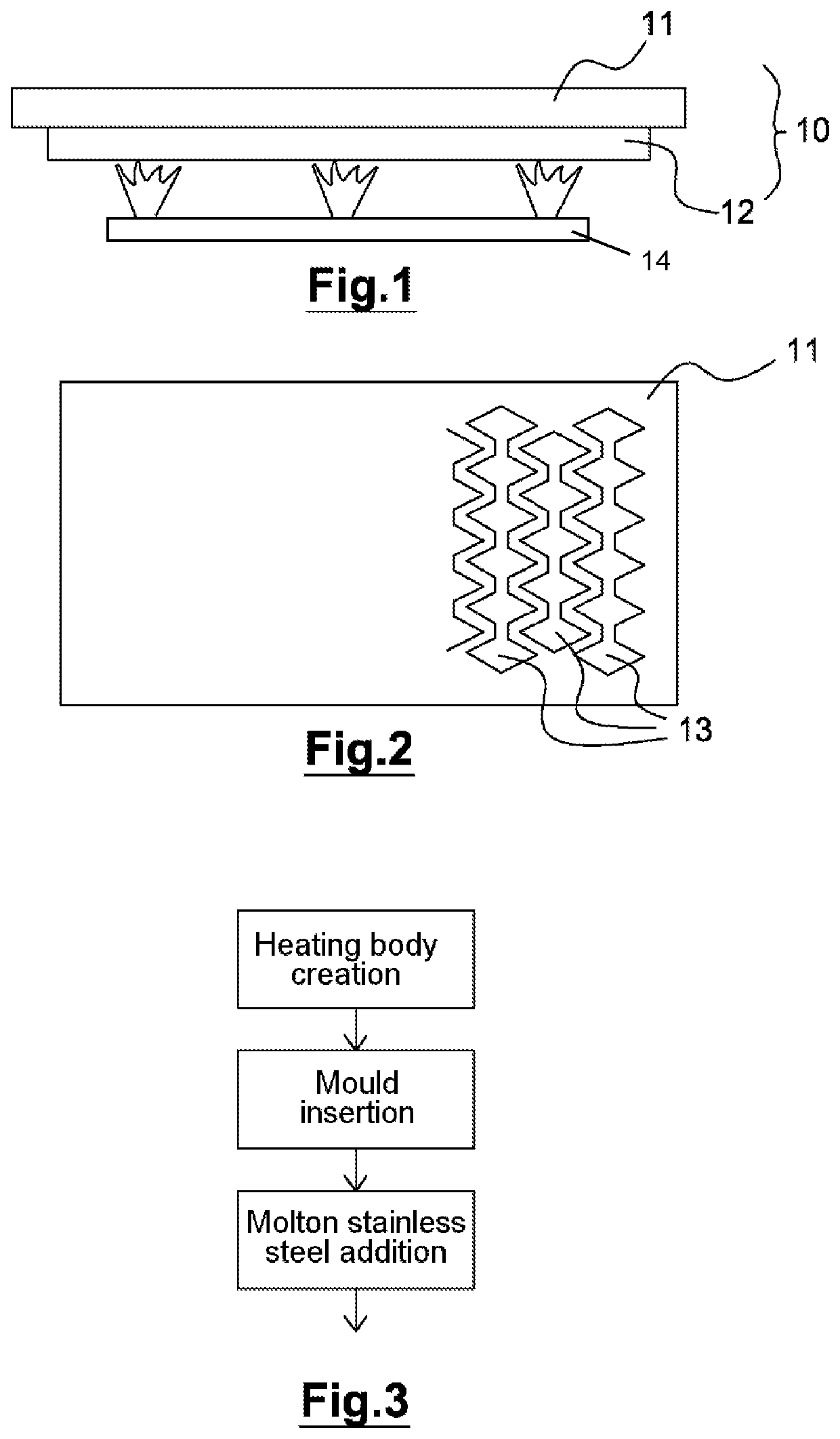
[0035]The invention falls within the scope of a cooking device using a cooktop with thermal inertia. The description relates only to the cooktop itself. The burners and other elements of the heating device are assumed to be known per se. As such, they depart from the scope of the present invention, and therefore are not detailed further here.

[0036]As is seen in FIG. 1, which illustrates a side view of such a cooking device comprising the cooktop 10 comprising two stacked plates 11, 12, and a single heater 14.

[0037]The top plate 11 is the actual cooking surface. It is intended to receive the food to be cooked, with which it therefore comes into contact. The top plate in this case is rectangular, but any other shape related to the conditions of use may be feasible. It is, in this case, made of food-grade stainless steel of a type known per se. Food-grade stainless steel is a stainless steel-type alloy, for example iron+chrome (at least 13%)+nickel+carbon, with proportions of these mat...


PUM

PropertyMeasurementUnit
thicknessaaaaaaaaaa
thicknessaaaaaaaaaa
thicknessaaaaaaaaaa

Abstract

A food cooking appliance includes a panel having a thermal inertia, and a heater to heat the panel from the bottom face thereof. The panel has at least two plates that lie on top of each other. Plates are made of different materials and are in close contact with one another across part of the facing surfaces thereof. The upper plate being suitable to receive the food to be cooked, and is made of stainless steel or titanium. The lower plate is made of cast iron. A method for manufacturing a panel consisting of two metal plates that are made of different materials and are bonded together in a metal casting process.

Description

RELATED APPLICATIONS[0001]This application is a continuation-in-part of application Ser. No. 15 / 735,202 filed Dec. 11, 2017, which is a § 371 application from PCT / FR2016 / 051406 filed Jun. 10, 2016, which claims priority from French Patent Application No. 15 55371 filed Jun. 12, 2015, each of which is incorporated herein by reference in its entirety.TECHNICAL FIELD[0002]The present invention falls within the field of food cooking devices.[0003]It relates more particularly to a device of high-thermal inertia griddle type, in particular of the type known usually as a “plancha”. The invention also relates to a method of manufacturing such a griddle.BACKGROUND OF THE INVENTION[0004]Cooking food on a top with a high thermal inertia has been known for many years. It makes it possible to cook food, for example meat, with a great consistency of applied heat, as well as a uniform temperature over the entire cooktop, and therefore, over the entire food being cooked. Such devices are, for examp...

Claims


Application Information

Patent Timeline
Patent Type & Authority Applications(United States)
IPC IPC(8): A47J36/02A47J37/06B22D19/04
CPCA47J36/02B22D19/04A47J37/0682
Inventor LAMPAERT, RÉMY
Owner SISTERIA
Learn More