Apparatus for working on metal containers

a technology for working on metal containers and apparatuses, applied in lighting and heating apparatus, furniture, charge manipulation, etc., can solve the problems of unsuitable for moving complex shaped containers, high the effect of reducing the number of passages and thus the number of transfers

Inactive Publication Date: 2010-10-07
MALL HERLAN SCHWEIZ AG
View PDF7 Cites 0 Cited by
  • Summary
  • Abstract
  • Description
  • Claims
  • Application Information

AI Technical Summary

Benefits of technology

[0013]More in particular, the object of the present invention is to provide an apparatus for working on metal containers which should ensure steady and safe passage at high speed thereof, from one working tower to the next one, irrespective of the mass moved without directly acting on the side surface of the metal container.
[0014]A further object of the present invention is to provide an apparatus which during the transport of the metal containers from one working tower to the next one, should allow high phase displacement without any consequences on the process.
[0015]A further object of the present invention is to provide an apparatus easy to disassemble and maintain.
[0016]A further object is to provide a transport apparatus that Is able to manage different combinations of complexity of the product and productivity, allowing the metal container to undergo even multiple different processes on the same tower.
[0017]A further object of the present invention is to provide the users with a transport apparatus suitable for ensuring high level of resistance and reliability over time, also such as to be easily and inexpensively constructed.

Problems solved by technology

A drawback of the conventional transport devices lies in the fact that they are unsuitable for moving complex shaped containers, such as those of the “bottle can” and / or “contour can” type, increasingly requested on the market.
In fact, such types of containers present complex shaping of the side surface that requires a high number of passages and a reduced cylindrical portion for gripping.
The high number of passages and thus, of transfers “worsens” the traditional method of pick up with vacuum technique, since the use of guides for the direct conveying of the metal conveyors causes scratching that, if repeated, can cause damages to the side surface of the containers themselves.
Moreover, the reduced cylindrical portion and the shape of the container makes the vacuum pick up, already “critical” for simple containers (of the “pop-can”) difficult; the use of such technique implies a certain percentage of loss during the transfer from one working tower to the next one.
A further drawback is that the current transport devices present limits as regards the pick up strength that can be exerted on the containers and the movable mass.
A further drawback is that the traditional transport devices do not allow a high phase displacement between one working tower and the next one, without inducing faults and causing the reject of the container or the machine stoppage.
A further drawback is that such transport system is characterised by long tooling before operations on a container of different format can be carried out.

Method used


Image

  • Apparatus for working on metal containers
  • Apparatus for working on metal containers
  • Apparatus for working on metal containers

Examples


Embodiment Construction

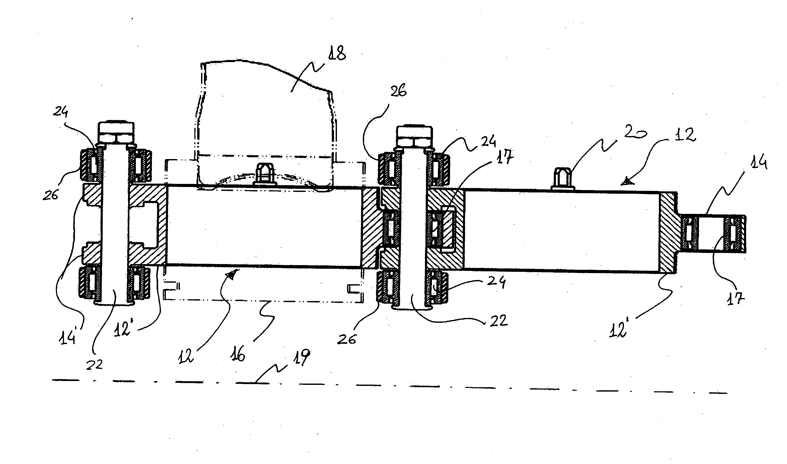
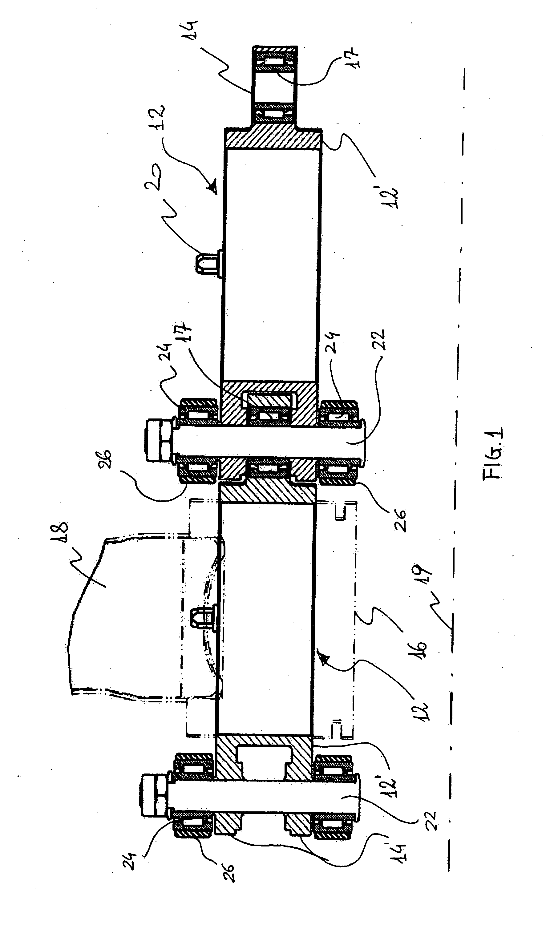
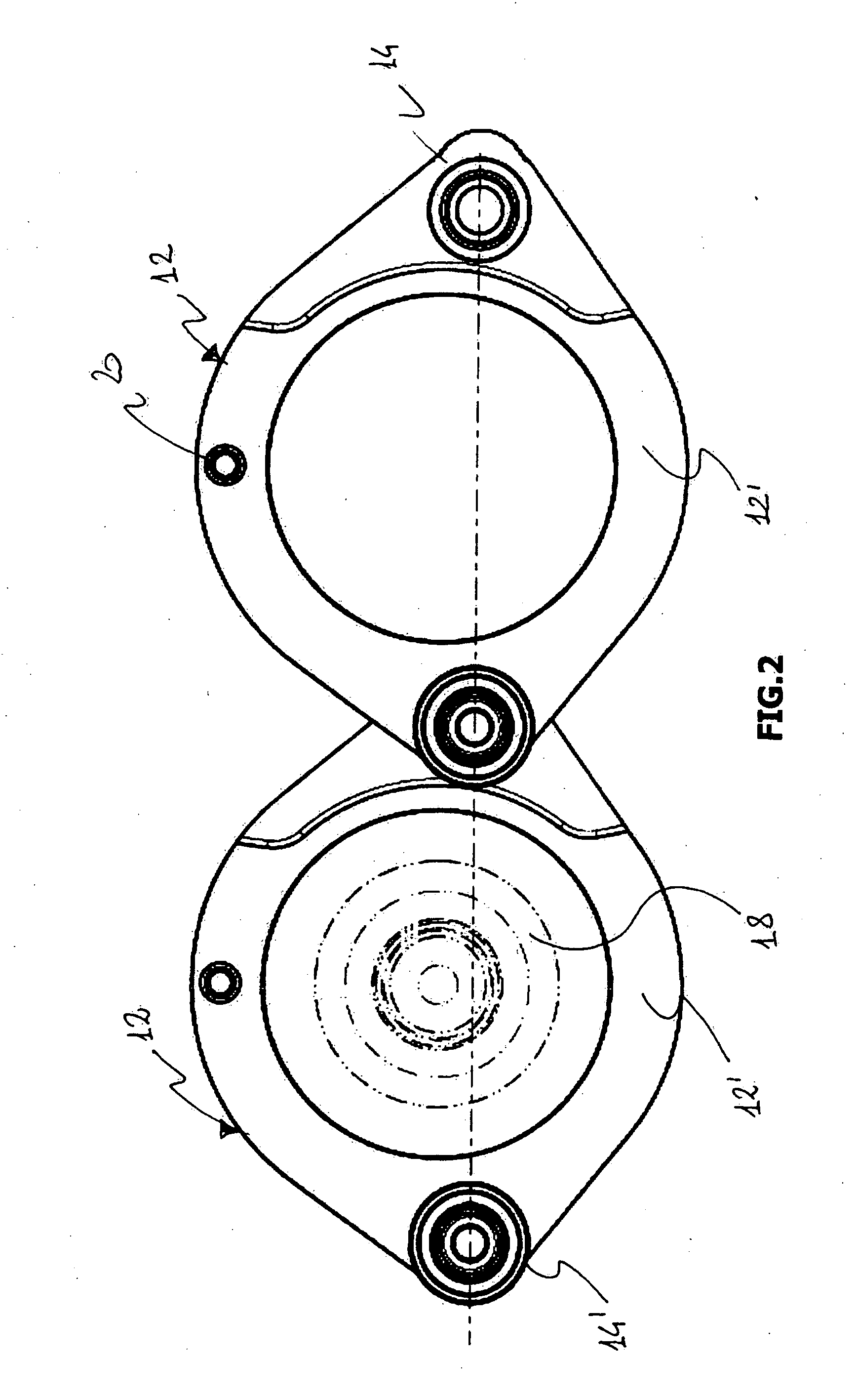
[0023]With reference to the above figures, the apparatus for working on metal containers of the present invention, globally indicated with 10 at FIG. 3, comprises a plurality of elements 12 shaped and connected to each other, according to the methods detailed hereinafter, for defining a closed chain and partially wound on multiple driving wheels 13 and idle or transfer wheels 15 of a high speed continuous machine not shown in the figures. The idle or transfer wheels 15 have the function of “routing” the chain composed of elements 12 according to a path defined depending on the design choices; some of the above idle wheels, moreover, define tighteners whose function is to keep the chain always tightened and compensate the irregularity thereof, due to dynamic strains, due to the polygonal effect of the chain. The driving wheels 13, on the other hand, are responsible for pulling the chain and are substantially at the machine working towers. In an alternative embodiment the chain is mov...


PUM

PropertyMeasurementUnit
anti-frictionaaaaaaaaaa
lengthaaaaaaaaaa
thicknessaaaaaaaaaa

Abstract

An apparatus (10) for working on metal containers, especially suitable for high speed machines and intended for performing a sequence of operations on the metal containers themselves including a chain composed of a plurality of elements (12) linked in a succession and cooperating in simultaneous transporting and processing of metal containers.

Description

TECHNICAL FIELD[0001]The present invention relates to an apparatus for working on metal containers.[0002]More in particular, the present invention relates to an apparatus for working on metal containers to be used especially in high speed machines that operate in continuous and intended for performing a sequence of operations on the side surface of the metal containers themselves.BACKGROUND ART[0003]Metal containers subject to mechanical processes on said machines basically are those obtained in aluminium, alloys thereof, steel or other suitable materials with which containers for the beverage, food field or technical use are obtained; such metal containers, before being subject to the multiple operations in a sequence that modify the outer side surface thereof, can be subject to preliminary inner and / or outer coating and lithography of the outer side surface.[0004]The metal containers processed on such types of machines preferably are subject to different types of processes by plas...

Claims


Application Information

Patent Timeline
Patent Type & Authority Applications(United States)
IPC IPC(8): B65G47/00
CPCB21D51/2692B65G2201/0252B65G17/44B65G17/40
Inventor FRATTINI, ROBERTO
Owner MALL HERLAN SCHWEIZ AG
Why Eureka
Try Eureka