
Accuracy diagnostic device and accuracy diagnostic method for machine tool

a diagnostic device and diagnostic method technology, applied in the direction of process, machine control, process control, etc., can solve the problems of increasing the error thermal displacement occurs, and accuracy limitation of thermal displacement correction, so as to achieve the effect of high accuracy and easy making of the required accuracy

Pending Publication Date: 2022-01-13
OKUMA CORP
View PDF0 Cites 0 Cited by
  • Summary
  • Abstract
  • Description
  • Claims
  • Application Information

AI Technical Summary

Benefits of technology

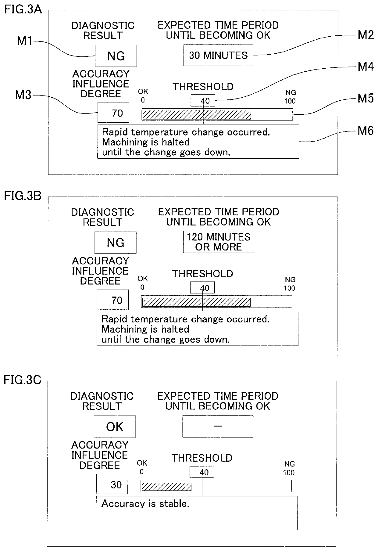
The invention allows for predicting accurately how a machine tool will behave due to temperature changes. It also predicts the time it will take for the machine tool to stabilize to the desired accuracy. This information is displayed so that an operator can see when the machine tool is ready to use again. This improves the efficiency of machining and enables better planning for production.

Problems solved by technology

When a machining is performed using a machine tool, a room temperature change in a factory causes a thermal deformation, such as an expansion and a bending of the machine tool structure, and consequently, a thermal displacement occurs.
However, the thermal displacement correction has a limitation in accuracy, and an error occurs when the temperature change is large.
Especially, when the room temperature rapidly changes at starting up of an air conditioner and the like, it is considered that the error of the thermal displacement correction increases.
However, since the machining cannot be performed while the accuracy is diagnosed as being degraded, and it is not known when the machine tool accuracy is stabilized again to allow starting the machining, a production plan can no longer be made.

Method used


Image

  • Accuracy diagnostic device and accuracy diagnostic method for machine tool
  • Accuracy diagnostic device and accuracy diagnostic method for machine tool
  • Accuracy diagnostic device and accuracy diagnostic method for machine tool

Examples


Embodiment Construction

[0019]The following describes embodiments of the disclosure based on the drawings.

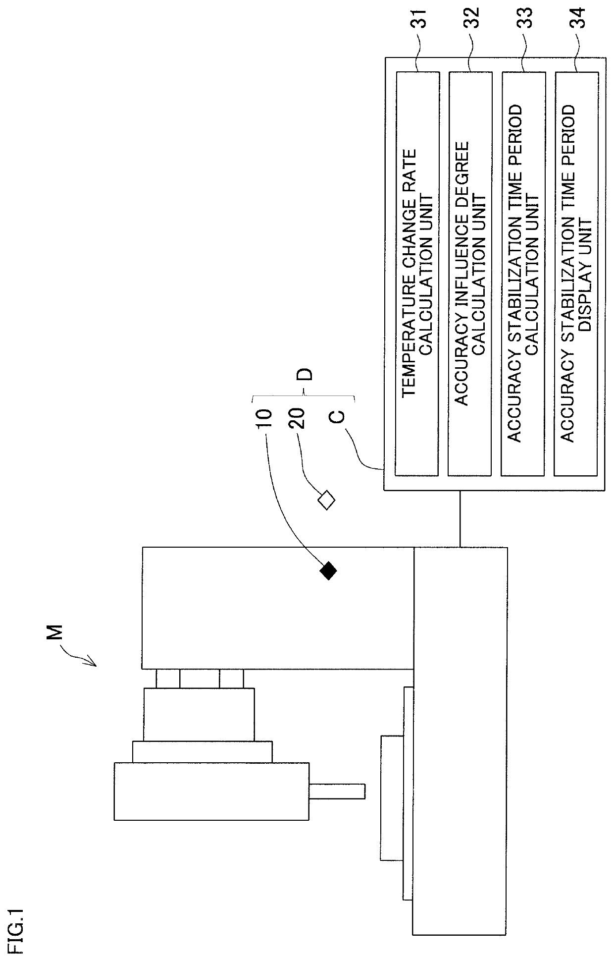
[0020]FIG. 1 illustrates an exemplary machine tool (vertical type machining center) to which the disclosure is applied. In FIG. 1, for easily understanding the machine structure, illustrations of a cover covering an outer periphery of a machine tool M and the like are omitted. The applicable machine tool may be a machine tool having another configuration, such as a machining center having a configuration other than the vertical type machining center, a lathe, or a grinder.

[0021]A machine body temperature sensor 10 and an environmental temperature sensor 20, which measures an ambient room temperature and / or a temperature of a cutting fluid, are mounted to the machine tool M, and the machine tool M is connected to a control device C. While one machine body temperature sensor 10 and one environmental temperature sensor 20 are illustrated in FIG. 1, a plurality of machine body temperature sensors 10 and a ...


PUM


Abstract

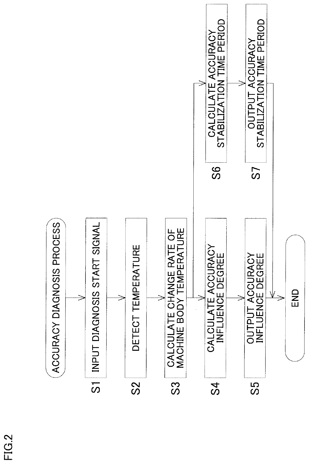
An accuracy diagnostic device that diagnoses an influence on an accuracy of a machine tool due to a thermal deformation includes a temperature change rate calculation unit, an accuracy influence degree calculation unit, and an accuracy stabilization time period calculation unit. The temperature change rate calculation unit calculates a rate of a temperature change in a predetermined portion of the machine tool as a temperature change rate. The accuracy influence degree calculation unit calculates an influence degree on the machine tool accuracy due to the thermal deformation as an accuracy influence degree, based on the temperature change rate. The accuracy stabilization time period calculation unit calculates a time period until the machine tool accuracy is stabilized as an accuracy stabilization time period, based on the temperature change rate.

Description

BACKGROUND OF THE INVENTION[0001]This application claims the benefit of Japanese Patent Application Number 2020-117310 filed on Jul. 7, 2020, the entirety of which is incorporated by reference.FIELD OF THE INVENTION[0002]The disclosure relates to a device and a method for predicting and diagnosing an influence on a machine tool accuracy when a temperature of the machine tool itself or a temperature of an environment in which the machine tool is installed changes.DESCRIPTION OF RELATED ART[0003]When a machining is performed using a machine tool, a room temperature change in a factory causes a thermal deformation, such as an expansion and a bending of the machine tool structure, and consequently, a thermal displacement occurs. The thermal displacement changes a positional relation between a tool mounted to the machine tool and a workpiece, thus degrading a machining accuracy of the workpiece.[0004]As a method for suppressing the thermal displacement of machine tool, there has been wid...

Claims


Application Information

Patent Timeline
Patent Type & Authority Applications(United States)
IPC IPC(8): G01B21/32G01B21/16
CPCG01B21/32G01B21/16B23Q17/00G05B19/406G05B2219/37431
Inventor MIZOGUCHI, YUJI
Owner OKUMA CORP
Learn More