
Method And Device For Measuring The Thickness And The Electrical Conductivity Of An Object Of Measurement

Active Publication Date: 2007-11-29
ABB (SCHWEIZ) AG
View PDF10 Cites 4 Cited by
  • Summary
  • Abstract
  • Description
  • Claims
  • Application Information

AI Technical Summary

Benefits of technology

[0042] Thus, the present invention solves the problem of making the magnetic measurement technique generally applicable. A user of the technique disclosed in SE 517 293 need not completely change the basic technique when sheet of a thin thickness is to be measured. The invention allows the measurement for thin sheet to be carried out with the same type of equipment and method.

Problems solved by technology

This technique never became really industrially accepted and applied since the measurement of the thickness of an object was influenced far too much by the composition of the material.
One disadvantage of this new technique, however, has been that it has not been possible to use it for measuring very thin sheets such as, for example, metal foil.
This is a considerable disadvantage, since an industrial measurement technique should be generally applicable and be able to measure sheets of different thicknesses and of different material properties.
The measured value is, however, also influenced by the composition of the material, so the accuracy of measurement is not sufficiently good.
However, when measuring on sheet or strip, it has proved that it has not been possible to fulfil the highest demands for accuracy of measurement.
Measurement at several points in time, and calculations based on these measured values, result in too large total errors.
However, one problem is that the technique cannot be used when measuring very thin sheet and strip.
When the actual measurement is to be performed, that is, during a somewhat later period of time, the effect of the change has already ceased and no useful measured value is obtained.
Not being able to measure on thin sheet and strip means that the usefulness of the method is considerably reduced, since the same user of the method often wants to be able to use the measuring device on both thick and thin sheets.
Other technique must therefore be procured and used in parallel, which results in additional costs, etc.
These problems of the existing technique constitute serious problems which limit the reliability of known techniques and hence their usefulness.
One important problem that needs to be solved is that prior art known methods of measurement and devices cannot be used for measuring thin or very thin sheets such as, for example, metal foil.
Prior art measuring devices and methods have not been able to fulfil the requirements for accuracy of measurement, not even when using inductive methods.
Calculations based on such measurement values have resulted in too large errors.
Another problem of the prior art is that measurement of, for example, the thickness of a product is influenced by the material composition of the object to be measured.
A further problem is that different methods and measuring devices must be used in parallel today in order to carry out measurements of both thin and thick sheets.
An additional problem is that the manufacture of strip and sheet is a power-demanding process, and in connection with accidents there is always a risk that meters, such as thickness meters, are damaged or destroyed.

Method used


Image

  • Method And Device For Measuring The Thickness And The Electrical Conductivity Of An Object Of Measurement
  • Method And Device For Measuring The Thickness And The Electrical Conductivity Of An Object Of Measurement
  • Method And Device For Measuring The Thickness And The Electrical Conductivity Of An Object Of Measurement

Examples


Embodiment Construction

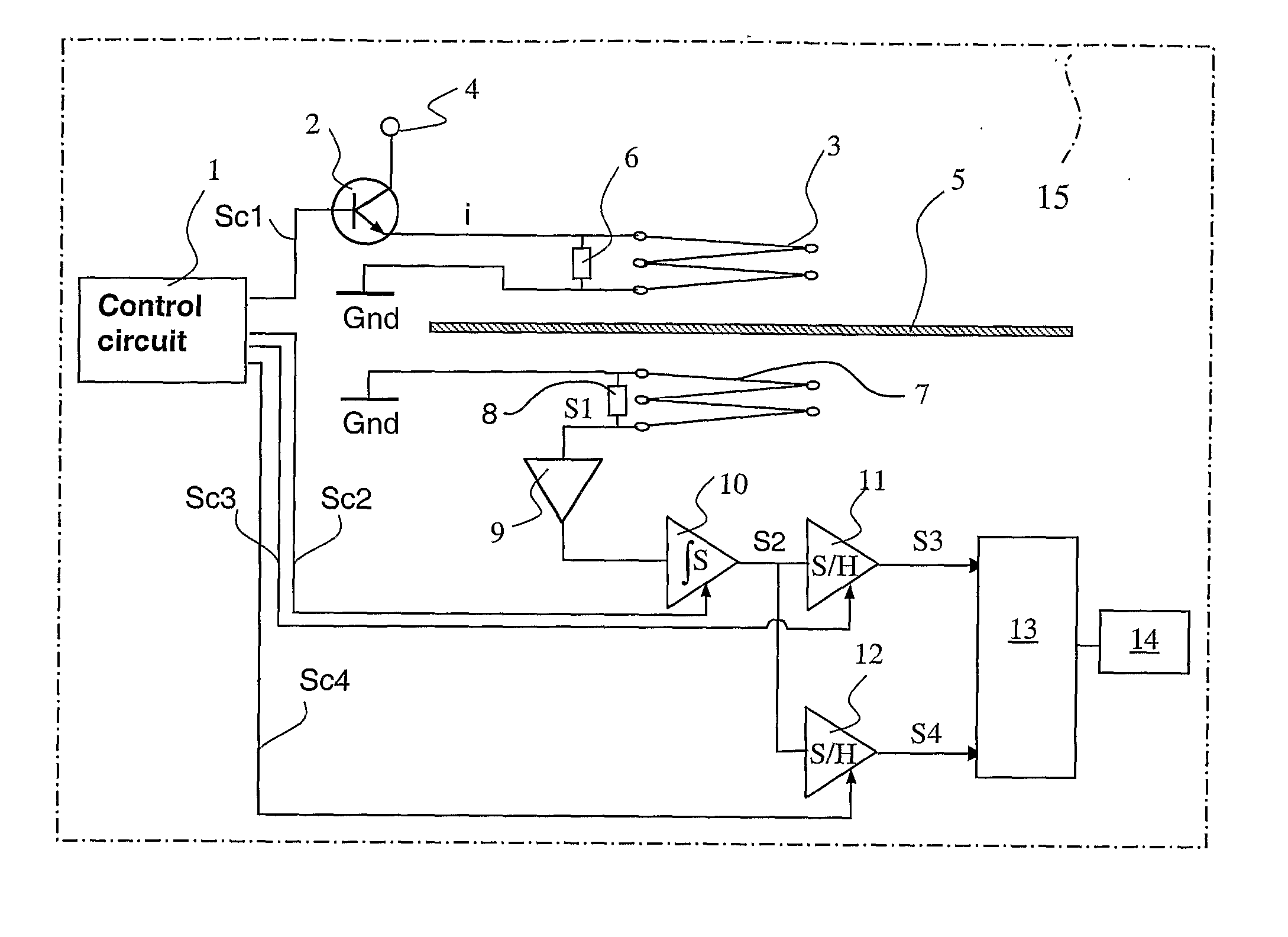
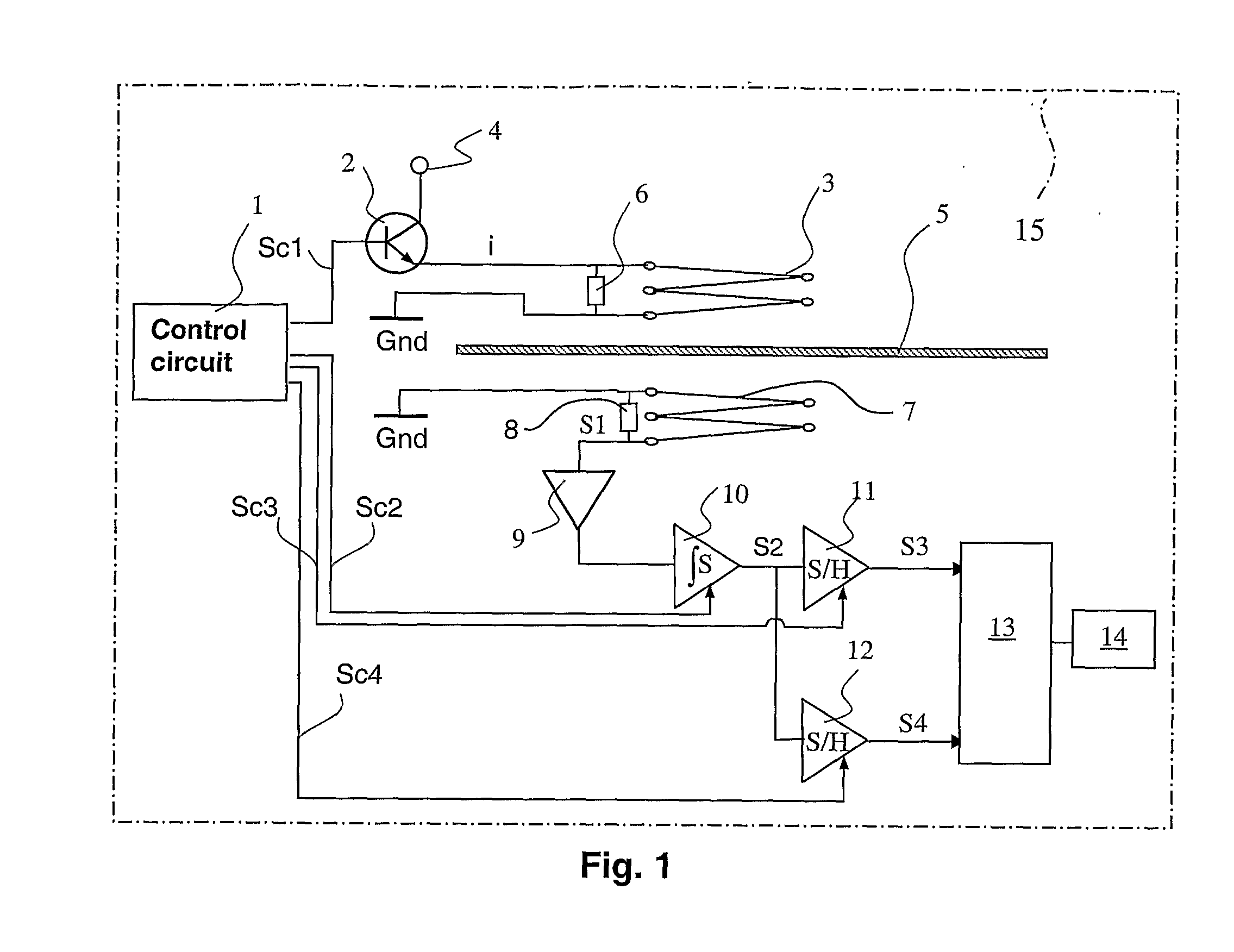
[0050]FIG. 1 shows a circuit diagram according to the invention for measuring thickness and conductivity of an object, or an object 5 to be measured, and its electrical properties. The object 5 to be measured, here in the form of a sheet, is placed between a transmitter coil 3 and a receiver coil 7.

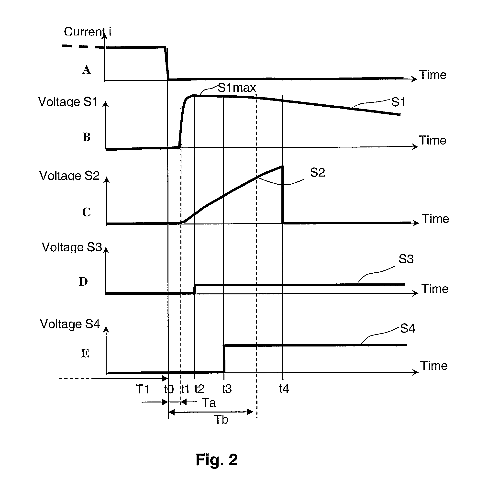
[0051] The transmitter coil 3 is fed, during a first period of time T1, with a substantially constant current i which comes from a current source 4 via a transistor 2. The transistor 2 is controlled by a signal Sc1 from a control circuit 1.

[0052] During a first period of time T1, a current-feed period, the transistor 2 carries current from the current source 4 to the transmitter coil 3 and further to ground Gnd. Directly after this current-feed period T1, the current to the transmitter coil 3 is interrupted by the transistor 2 shutting off. A resistor 6 across the transmitter coil 3 serves as a discharge resistor in connection with the interruption of the current.

[0053] This resistor 6...


PUM


Abstract

A method for non-contact measurement of a dimension and / or an electrical property in an electrically conducting object to be measured by using electromagnetic induction. An electromagnetic field is brought to penetrate through the object to be measured. A transmitter coil is place on one side of the object to be measured. A receiver coil is placed on the other side of the object to be measured. A magnetic field is generated in the transmitter coil. A sudden change is generated in the magnetic field generated in the transmitter coil from one level to another. The voltage induced in the receiver coil is detected. The period of time that elapses from the time of the change of the magnetic field in the transmitter coil up to the time when a voltage starts to be induced in the receiver coil is determined. The magnitude of the induced voltage is determined. The thickness and / or electrical conductivity of the object to be measured is calculated.

Description

TECHNICAL FIELD [0001] The present invention relates primarily to non-contact measurement / determination of the sought properties or parameters of an object to be measured, such as, for example, geometrical dimensions or electrical properties. These may be the thickness or electrical conductivity of the object to be measured. The invention relates specifically to non-contact measurement that utilizes electromagnetic induction and measures on electrically conductive but substantially non-magnetic objects such as, for example, metal products. [0002] One particular field of application is thickness measurement in the manufacture of metal sheets, metal strip, etc., and, for example, where it is necessary to continuously measure the thickness of the sheet to be able to increase the final quality of the sheet or strip. [0003] The invention may also be used for measuring non-metallic, but electrically conductive, objects. [0004] The invention is especially suited for non-contact and simulta...

Claims


Application Information

Patent Timeline
IPC IPC(8): G01B7/06B60KG01B7/02G01R27/00
CPCG01B7/10G01B2210/46G01R27/00
Inventor LINDER, STEN
Owner ABB (SCHWEIZ) AG
Learn More