Hybrid evaluation of radar data for classifying objects

a technology of object classification and radar data, applied in the direction of reradiation, measurement devices, instruments, etc., can solve the problem that the type of object cannot be recognized directly from radar signals, and achieve the effect of less computing time, less resource requirements, and easy training

Pending Publication Date: 2022-01-13
ROBERT BOSCH GMBH
View PDF0 Cites 0 Cited by
  • Summary
  • Abstract
  • Description
  • Claims
  • Application Information

AI Technical Summary

Benefits of technology

[0011]It has been found that in this way the classifier may be designed with a significantly lower resource requirement and requires much less computing time. The reason for this is that the classifier is not fed the entire frequency spectrum all at once, but instead only a small fraction of this frequency spectrum. In particular, a setting in which multiple objects are located may be successively classified. For this purpose, the groups of locations with radar reflexes indicating the presence of different objects are processed one after the other. The class assignment of the object, the presence of which is indicated by the group, is thus obtained for each of these groups.
[0012]The classifier is therefore also easier to train since the classifier only has to learn to recognize individual objects, but not interactions that may occur when attempting to recognize multiple objects simultaneously.
[0013]In one particularly advantageous embodiment of the present invention, based on the group, more of the locations from which reflected radar radiation has reached the radar sensor are selected. The selection depends on the extent to which it is plausible that the object characterized by the group has also reflected radar radiation from the additional location in question. Also for these additional locations, portions of the frequency spectrum are ascertained and included in the aggregation. Clustering, which divides the total amount of locations into groups, aims to find dividing lines between these groups which are plausible on average. This means that, in some cases, locations whose assignment to an object would still have been useful are no longer assigned to this object when clustering. Since additional locations are selected using the cluster, this effect is at least partially compensated. The fact that too many locations may be selected and therefore unnecessary portions of the frequency spectrum may be included in the aggregation is not further critical for the result of the classification.
[0014]In another particularly advantageous embodiment of the present invention, the locations for which portions of the frequency spectrum have been aggregated, and / or other features of radar reflexes received from these locations, are fed to the classifier together with the portions of the frequency spectrum. These other features may include for example the radar cross-section (RCS) and / or at least one angle (azimuth and / or elevation relative to the measuring location). The spatial information, and / or the information from the other features, and the information from the frequency spectrum may then interact particularly well so that the classifier may resolve the respective ambiguities of these two pieces of information and identify the object as unambiguously as possible and optimally resolve discrepancies. For example, the frequency spectrum also provides information as to whether the radar radiation coming from a particular location is rather reflected on an edge or on a surface. Furthermore, the frequency spectrum also depends on whether the radar radiation was rather reflected on a soft material or on a hard material. Some traffic-relevant objects, such as for example a bicycle with a rider, who in turn is wearing a helmet, may also be composites of soft and hard materials.

Problems solved by technology

However, the type of object may not be recognized directly from radar signals.
This means that, in some cases, locations whose assignment to an object would still have been useful are no longer assigned to this object when clustering.

Method used


Image

  • Hybrid evaluation of radar data for classifying objects
  • Hybrid evaluation of radar data for classifying objects

Examples


Embodiment Construction

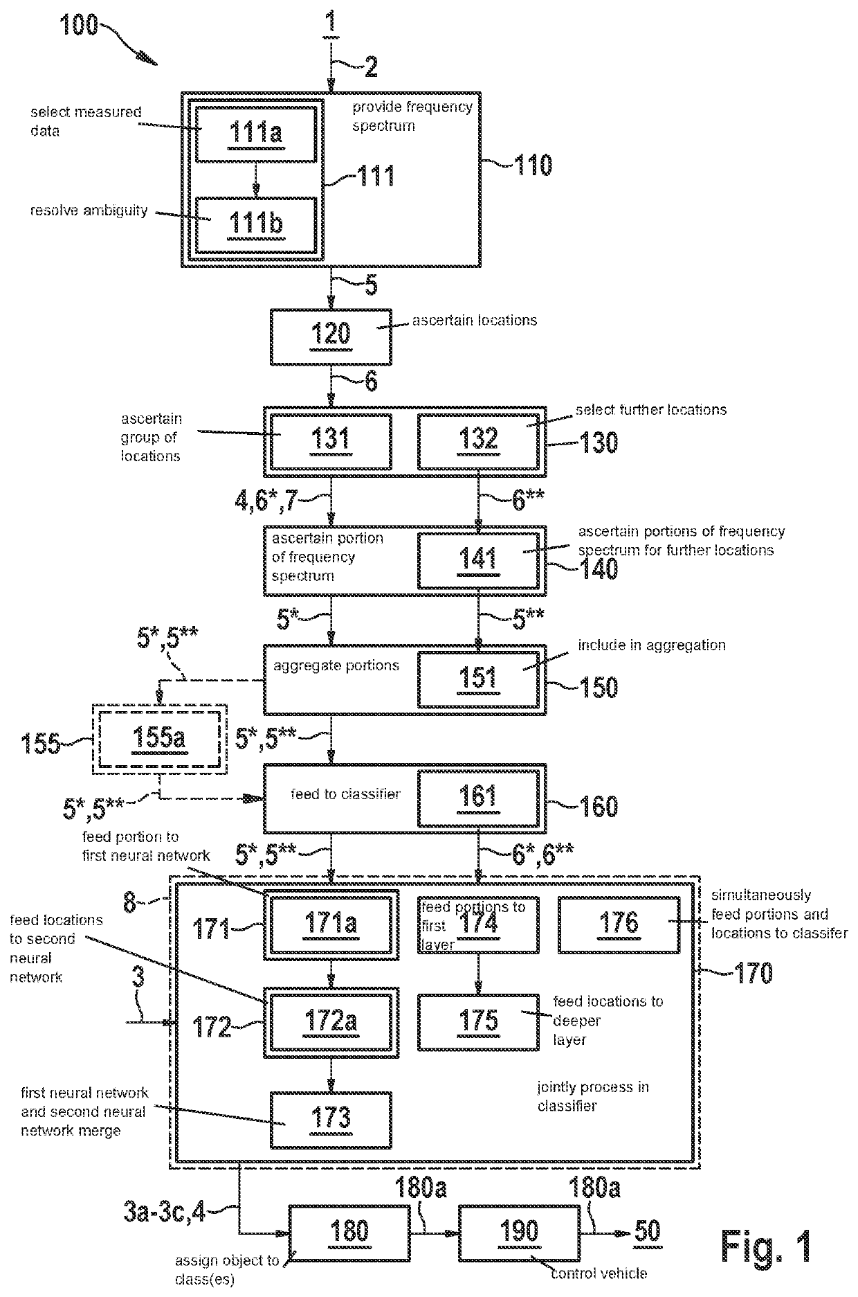
[0035]FIG. 1 is a schematic flowchart of an exemplary embodiment of method 100 for classifying measured data 2 recorded by at least one radar sensor 1, in accordance with the present invention.

[0036]In step 110, a frequency spectrum 5 of time-dependent measured data 2 from radar sensor 1 is provided. According to block 111, this frequency spectrum 5 may in particular be provided for example as a distance-speed representation. According to block 111a, measured data 2 recorded using radar radiation of modulation type JSFMCW may in particular be selected for example. According to block 111b, an ambiguity of these measured data 2 regarding the speed may then be resolved using any arbitrary additional piece of information.

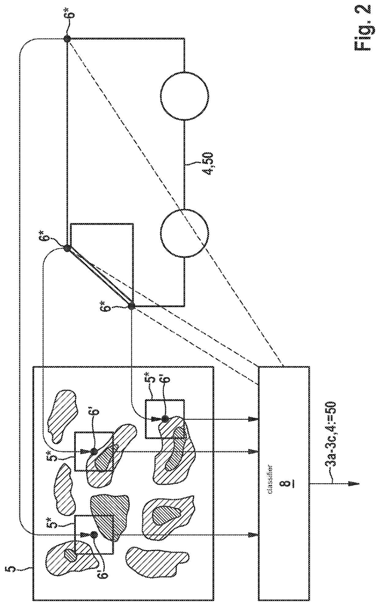
[0037]In step 120, from this frequency spectrum 5, locations 6 from which reflected radar radiation has reached radar sensor 1 are ascertained. In step 130, at least one group 7 of such locations 6* belonging to one and the same object 4 is ascertained. In step 140, for...


PUM


Abstract

A method for classifying objects based on measured data recorded by at least one radar sensor. In the method, a frequency spectrum of time-dependent measured data of the radar sensor is provided; from this frequency spectrum, locations from which reflected radar radiation has reached the radar sensor are ascertained; at least one group of such locations belonging to one and the same object is ascertained; for each location in this group, a portion of the frequency spectrum that corresponds to the radar radiation reflected from this location is ascertained; all these portions for the object are aggregated and are fed to a classifier; the object is assigned by the classifier to one or multiple classes of a predefined classification.

Description

CROSS REFERENCE[0001]The present application claims the benefit under 35 U.S.C. § 119 of German Patent Application No. DE 102020208544.7 filed on Jul. 8, 2020, which is expressly incorporated herein by reference in its entirety.FIELD[0002]The present invention relates to the evaluation of radar data for classifying objects, the presence of which is indicated by these radar data.BACKGROUND INFORMATION[0003]For a vehicle to be able to move in an at least semi-automated manner in road traffic, it is necessary to detect the surroundings of the vehicle and to initiate countermeasures if there is a threat of collision with an object in the surroundings of the vehicle. For safe automated driving, it is also necessary to create a surroundings representation and localization.[0004]Detecting objects with the aid of radar does not depend on the lighting conditions and is possible for example even at night over a relatively large distance without the oncoming traffic being blinded by high beams...

Claims


Application Information

Patent Timeline
Patent Type & Authority Applications(United States)
IPC IPC(8): G01S7/41
CPCG01S7/411G01S13/931G01S7/417G01S13/04G01S13/32G01S13/584
Inventor RAMBACH, KILIANMORGAN, LISA-KRISTINACOZMA, ADRIANA-ELIZA
Owner ROBERT BOSCH GMBH
Why Eureka
Try Eureka