Deconding method, decoding device, and communication system

A technology for decoding devices and communication systems, applied in transmission systems, AM carrier systems, digital transmission systems, etc., can solve the problems of high implementation complexity, large implementation resources, and lack of realizability

Active Publication Date: 2014-01-08
HUAWEI TECH CO LTD
View PDF3 Cites 25 Cited by
  • Summary
  • Abstract
  • Description
  • Claims
  • Application Information

AI Technical Summary

Problems solved by technology

The implementation complexity of this method is very high, especially in the application of high-speed optical transmission systems, the overhead of FEC is relatively limited (about 7% to 30%), in this case, the high Th

Method used


Image

  • Deconding method, decoding device, and communication system
  • Deconding method, decoding device, and communication system
  • Deconding method, decoding device, and communication system

Examples


Embodiment 1

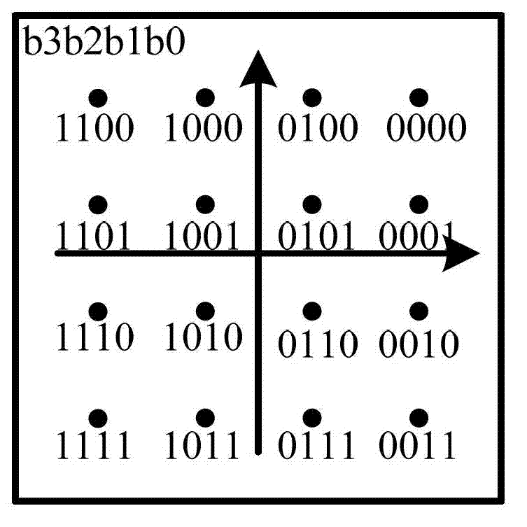
[0092] Due to the high-order modulation mapping, the bit error rate of different positions in the symbol is different, such as 16QAM Gray (Gray) mapping, the bit error rate (BER, Bit Error Rate) of the low bit (LSB, Least Significant Bit) b0b2 is the high bit ( BER, Most Significant Bit) 2 times the BER of b1b3. The core idea of ​​MLC is to use component codes of different rates to protect different information bits, so as to achieve overall performance optimization. For the error-prone LSB, use the low code rate FEC with higher error correction ability to protect; and for the MSB, because there is a large Euclidean distance between them, use the high code rate FEC with lower error correction ability to protect.

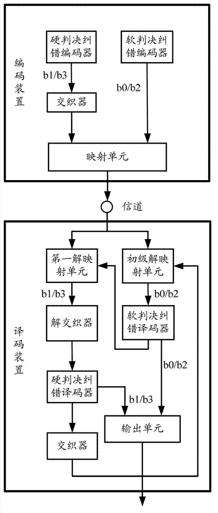
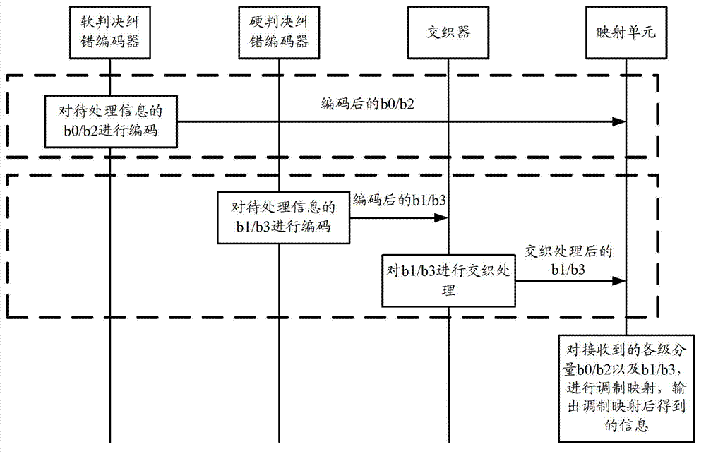
[0093]In this embodiment, 16QAM is used as an example. In this case, each 4-bit symbol of the information to be processed can be divided into two levels, and each 2-bit symbol can be divided into one level. Here, the bit classification is related to the modulation m...

Embodiment 2

[0145] In this embodiment, 32QAM is used as an example, if the Figure 7 In the mapping method shown, each 5-bit symbol of the information to be processed can be divided into three levels. The first level components are bits b0 and b1, which will be represented by b0 / b1 later, and the second level components are bits b2, the third-level components are bits b3 and b4, which will be represented by b3 / b4 later, where the order of bits of b0, b1, b2, b3, and b4 is from low to high.

[0146] Figure 6 It is a schematic diagram of the communication system provided by Embodiment 2 of the present invention. Similarly, the encoding device can be set at the information sending end, and the decoding device can be set at the information receiving end. The encoding device and decoding device in the communication system will be described separately below. Such as Figure 6 As shown, the encoding device includes: a soft-decision error correction encoder, a first hard-decision error correc...

Embodiment 3

[0163] In this embodiment, 32QAM is still used as an example, and each 5-bit symbol of the information to be processed is still divided into three levels. The first level components are bits b0 and b1, which will be represented by b0 / b1 later, and the second The first-level component is bit b2, and the third-level component is bit b3 and b4, which will be represented by b3 / b4 later, where the bit order of b0, b1, b2, b3, and b4 is from low to high. Different from the second embodiment, the third embodiment adopts a different implementation manner for the encoding and decoding of the third-level component.

[0164] Figure 8 A schematic diagram of the communication system provided by Embodiment 3 of the present invention, such as Figure 8 As shown, the encoding device includes: a soft-decision error correction encoder, a first hard-decision error correction encoder, a first interleaver, and a mapping unit.

[0165] In the encoding device, the processing of the soft-decision ...


PUM


Abstract

The invention provides a decoding method, a decoding device, and a communication system. Through a mixed mode of soft-decision error correcting coding and hard-decision error correcting coding, multi-grade coding is realized, and through a mixed mode of soft-decesion error correcting decoding and hard-decesion error correcting deconding, multi-grade decoding is realized, the advantages of the two modes are integrated: the system complexity and resource cost are reduced by replacing a multi-grade soft-decision error correcting coding and decoding mode with a primary soft-decesion error correcting coding and decoding mode; other grade hard-decision error correcting coding and decoding are carried out on the basis of the primary soft-decision error correcting coding and decoding, thus the gain performance is guaranteed, and the requirement on gain for a high-speed light transmission system is fulfilled.

Description

technical field [0001] The present invention relates to coding technology in the technical field of information processing, and in particular to a decoding method, decoding device and communication system of a modulation and decoding system. Background technique [0002] The explosive growth of Internet services has promoted the transmission rate of optical transmission network lines to gradually develop from 40Gbps to 100Gbps, and then to 400Gbps or even 1Tbps. In high-speed optical transmission systems, higher spectral efficiency can be obtained by using high-order modulation methods, such as frequency-shift keying (FSK, Frequency-Shift Keying), differential phase-shift keying (DPSK, Differential Phase Shift Keying), positive High-order modulation methods such as QAM (Quadrature Amplitude Modulation). [0003] In 100Gbps and lower-speed optical transmission systems, the on-off keying (OOK, On-Off Keying) / quadrature phase shift keying (QPSK, Quadrature Phase Shift Keying) ...

Claims


Application Information

Patent Timeline
IPC IPC(8): H03M13/25
CPCH03M13/1111H03M13/2957H04L27/06H04L1/005H04L1/007H03M13/2792H03M13/3784H03M13/45H04L1/0045
Inventor 喻凡常德远
Owner HUAWEI TECH CO LTD
Why Eureka
Try Eureka