Projection control device, projection apparatus, projection control method, and projection control program

Active Publication Date: 2022-01-13
FUJIFILM CORP
View PDF1 Cites 0 Cited by
  • Summary
  • Abstract
  • Description
  • Claims
  • Application Information

AI Technical Summary

Benefits of technology

[0005]In JP2002-244813A, a mode in which the position of the icon displayed in accordance with the irradiation position is fixed for a certain period is disclosed. However, the mode is intended to increase a degree of freedom of the user by continuing display of the icon even in a state where use of the laser pointer is stopped, and cannot

Problems solved by technology

In a case where the irradiation position of the laser light slightly changes, a position of the image such as the icon displayed in accordance with the irradiation position also moves slightly, and it is difficult to perceive which position is pointed out, or an observer of the

Method used


Image

  • Projection control device, projection apparatus, projection control method, and projection control program
  • Projection control device, projection apparatus, projection control method, and projection control program
  • Projection control device, projection apparatus, projection control method, and projection control program

Examples


Example

First Modification Example

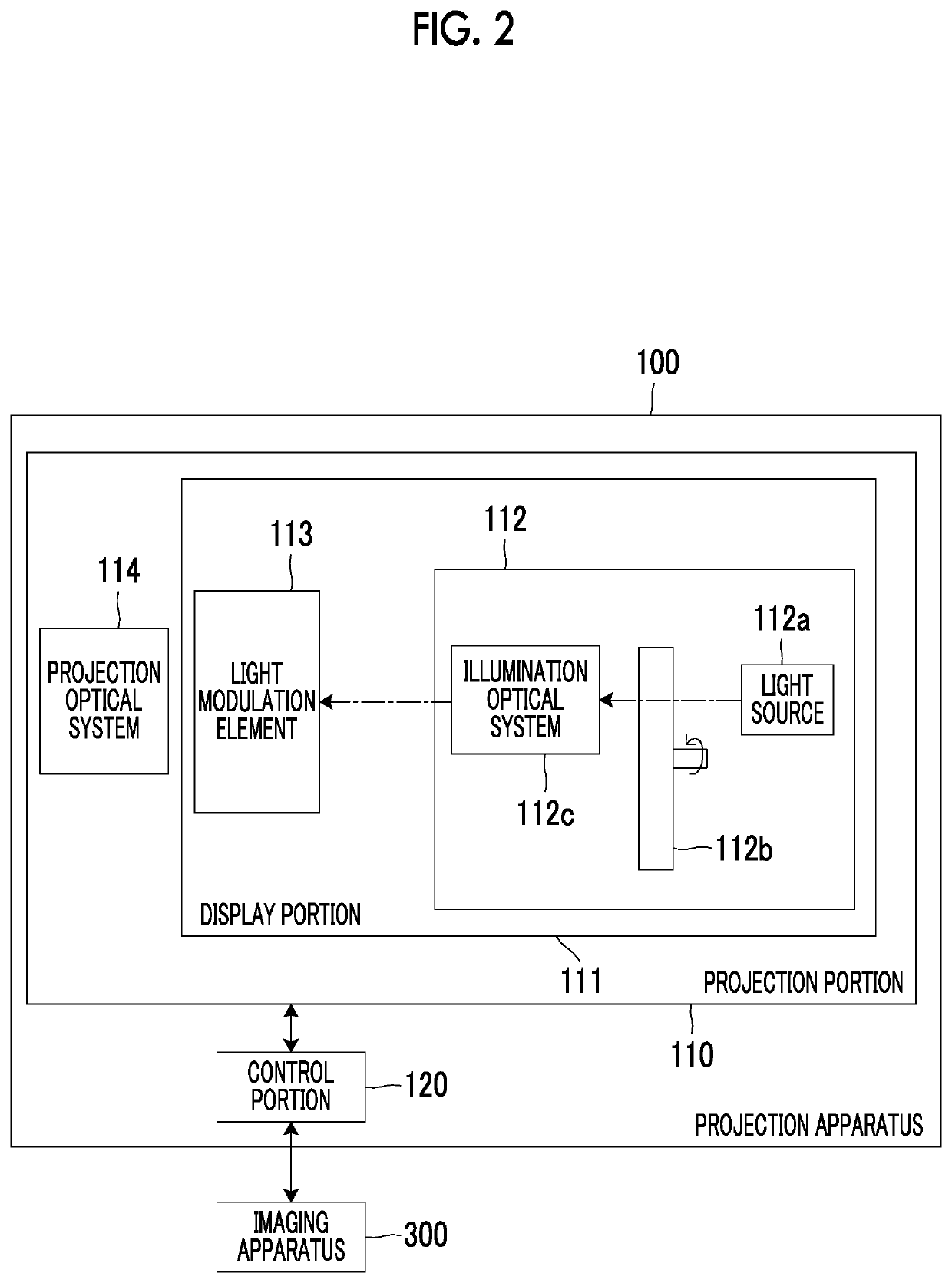
[0057]FIG. 8 is a function block diagram of a modification example of the control portion 120 of the projection apparatus 100 illustrated in FIG. 2. In the following description, the same constituents as described above will be designated by common reference numerals, and descriptions thereof may be appropriately omitted.

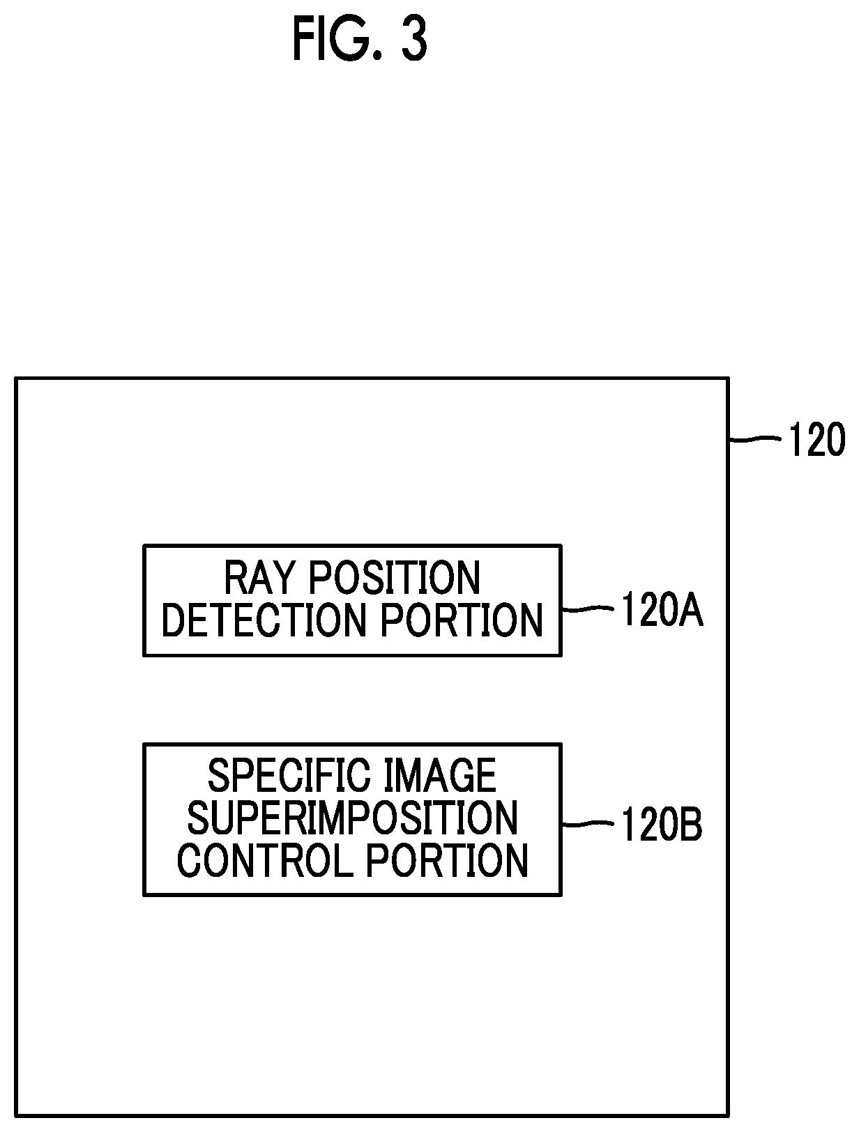
[0058]The control portion 120 illustrated in FIG. 8 functions as the ray position detection portion 120A, the specific image superimposition control portion 120B, and a range control portion 120C by executing the projection control program.

[0059]The range control portion 120C is a function block that controls the camera shake allowance range TR. The range control portion 120C changes a size of the camera shake allowance range TR automatically or based on an input operation performed by the user. The specific image superimposition control portion 120B of this modification example controls the superimposition position of the point-out icon im...

Example

Second Modification Example

[0062]FIG. 9 and FIG. 10 are descriptive diagrams for a modification example of a display control operation of the point-out icon image TG performed by the control portion 120 illustrated in FIG. 3. In this modification example, the specific image superimposition control portion 120B controls the superimposition position of the point-out icon image TG based on whether or not a movement state where the irradiation position P moves in one direction occurs a number of times greater than or equal to a first threshold value.

[0063]Specifically, each time the irradiation position P is detected by the ray position detection portion 120A after the region R is set, the specific image superimposition control portion 120B obtains a direction of a vector that has the irradiation position P as a terminal point and has the irradiation position P detected at an immediately previous detection timing of the irradiation position P as an initial point. In a case where a state...

Example

Third Modification Example

[0071]FIG. 11 is a function block diagram of another modification example of the control portion 120 of the projection apparatus 100 illustrated in FIG. 2. In the following description, the same constituents as described above will be designated by common reference numerals, and descriptions thereof may be appropriately omitted.

[0072]The control portion 120 illustrated in FIG. 11 functions as the ray position detection portion 120A, the specific image superimposition control portion 120B, and an image processing portion 120D by executing the projection control program.

[0073]In a case where a state where a change amount of the irradiation position P detected by the ray position detection portion 120A is less than or equal to a second threshold value continues, the image processing portion 120D performs correction processing for making a part corresponding to the irradiation position P in the image G not stand out on the image G The part corresponding to the ...


PUM


Abstract

A projection control device that controls a projection portion which projects an image to a projection surface includes a ray position detection portion that detects an irradiation position of a ray irradiated on the projection surface, and a specific image superimposition control portion that superimposes a predetermined specific image on a region corresponding to the irradiation position in the image. In a state where the specific image is superimposed on a first region corresponding to a first position detected by the ray position detection portion in the image, the specific image superimposition control portion, in a case where the irradiation position moves out of a predetermined range including the first position, moves the specific image to a region corresponding to the irradiation position that has moved, and in a case where the irradiation position moves within the range, continues superimposition of the specific image on the first region.

Description

CROSS REFERENCE TO RELATED APPLICATION[0001]This is a continuation of International Application No. PCT / JP2020 / 004414 filed on Feb. 5, 2020, and claims priority from Japanese Patent Application No. 2019-057126 filed on Mar. 25, 2019, the entire disclosures of which are incorporated herein by reference.BACKGROUND OF THE INVENTION1. Field of the Invention[0002]The present invention relates to a projection control device, a projection apparatus, a projection control method, and a projection control program.2. Description of the Related Art[0003]In a case of using a projector, for example, a laser pointer is used for pointing out any position on a displayed image. JP2017-220880A, JP2006-277085A, and JP2002-244813A disclose a projection apparatus that detects an irradiation position of laser light on a projection surface and superimposes an image such as an icon for making the position stand out on a projection image. In JP2002-244813A, it is disclosed that in a case where the irradiatio...

Claims


Application Information

Patent Timeline
IPC IPC(8): G09G5/38G09G3/00
CPCG09G5/38G09G3/002G09G2354/00G09G2320/0666G09G2340/0464G03B21/00G06F3/0481G09G5/08G06F3/042G06F3/03542G06F3/0386H04N9/3194H04N9/3179
Inventor INOUE, KAZUKIISHIZUKA, AKIHIROMASUDA, TOMONORIISHIDA, KAZUKI
Owner FUJIFILM CORP
Why Eureka
Try Eureka