

Anterior chamber perfusate for intraocular surgery and method
a technology of intraocular surgery and perfusate, which is applied in the field of medicine, can solve the problems of limiting the range of applications of gln, cell inactivation or even large areas of apoptosis and shedding, and achieves stable characteristic, high bioavailability, and resists high temperature sterilization
- Summary
- Abstract
- Description
- Claims
- Application Information
AI Technical Summary
Benefits of technology
Problems solved by technology
Method used
Image

Examples
embodiment 1
of Anterior Chamber Perfusate for Intraocular Surgery
[0031]The anterior chamber perfusate for intraocular surgery in this embodiment comprises the following components per 1 mL:
[0032]Sodium chloride 5.95-6.00 mg,
[0033]Potassium chloride 0.29-0.30 mg,
[0034]Calcium chloride 0.19-0.20 mg,
[0035]Sodium lactate 3.05-3.15 mg, and
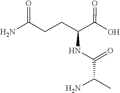
[0036]L-alanyl-L-glutamine 0.217-1.086 mg.
embodiment 2
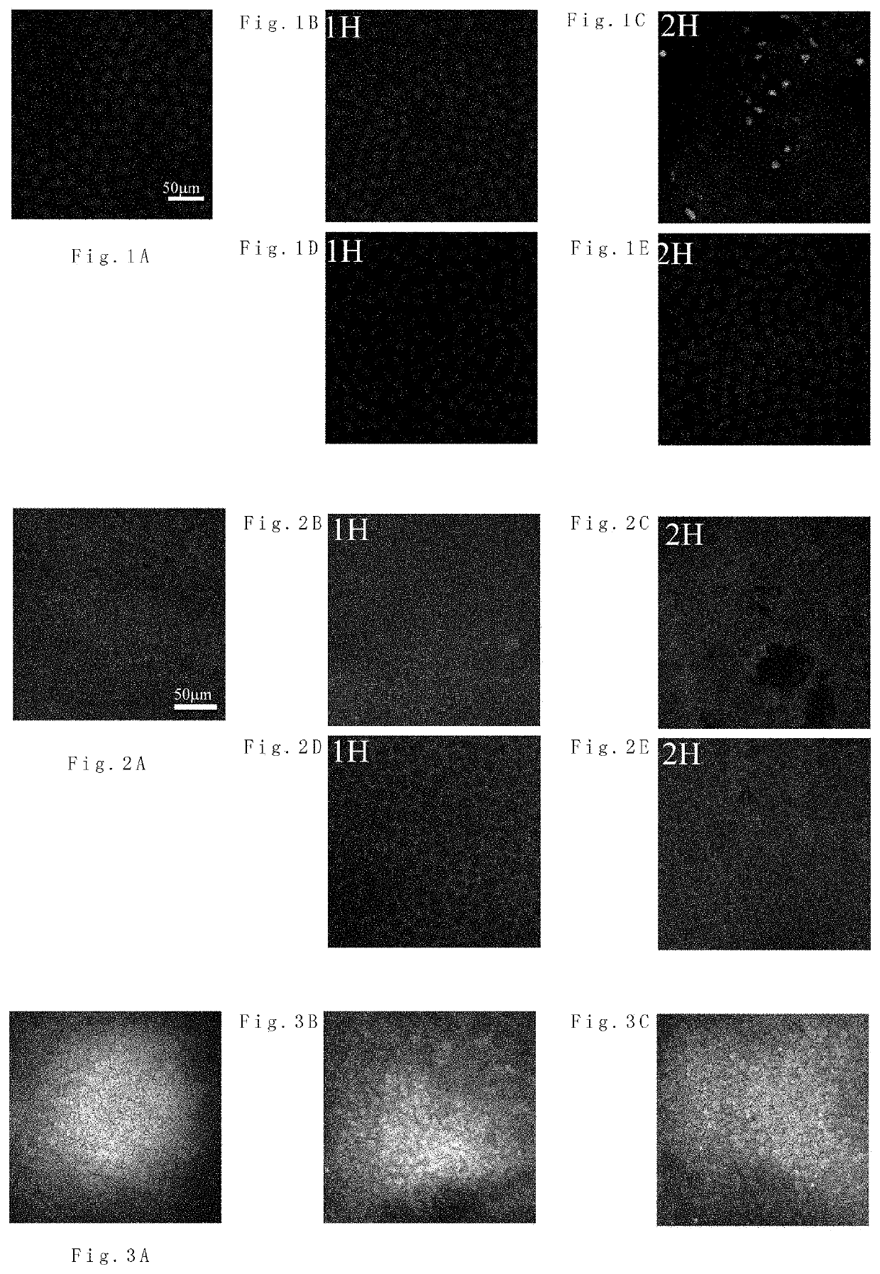
orneal Experiment and Anterior Chamber Perfusion Experiment Using the Anterior Chamber Perfusate
I. Subjects
[0037]30 healthy and clean ICR mice aged 6-8 weeks, weighing 20-25 g, and including male or female.
II. Experimental Reagents
[0038]L-alanyl-L-glutamine, Invitrogen™ Alexa Fluor™ 594 Phalloidin, Triton X-100, bovine Serum Albumin (BSA), phosphate buffer solution (PBS), pentobarbitone, acetone, compound tropicamide eye drops, and 4′,6-diamidino-2-phenylindole (DAPI) staining fluid.
III. Experimental Equipment
[0039]Operating microscope, a laser confocal scanning microscope (Olympus FV1000MPE-B, Olympus), and Heidelberg Retinal Tomography (HRT3).
IV. Experimental Method
[0040]1. Separating Cornea
[0041]The ICR mice were sacrificed by a cervical dislocation method, and eyeballs were taken off. After the eyeballs were washed by normal saline, mouse cornea was cut along corneal limbi, and irises, ciliary bodies, etc. were removed. The cornea was separated under the operating microscope to ...
PUM
| Property | Measurement | Unit |
|---|---|---|
| angle | aaaaa | aaaaa |
| temperature | aaaaa | aaaaa |
| intraocular pressure | aaaaa | aaaaa |
Abstract
Description
Claims
Application Information